Introduction to Airfoils
An airfoil is the cross-sectional shape of a wing, propeller blade, rotor, or turbine slice , essentially the profile you see when cutting across the wing's width. Understanding an airfoil's shape is crucial as it largely determines how the aircraft or rotor generates lift and experiences drag. For a broader understanding of how these shapes impact flight, see Understanding Aircraft Performance: A Comprehensive Overview of Flight Mechanics.
Key Airfoil Terminology
- Leading Edge: The rounded front part of the airfoil that first meets the airflow.
- Trailing Edge: The rear, usually sharper pointed part where the airflow exits.
- Chord Line: A straight line drawn from the leading edge to the trailing edge.
- Angle of Attack (α): The angle between the chord line and the oncoming airflow, typically ranging from 0° to 15° for most aircraft. Understanding the role of these forces during different phases such as takeoff can be supplemented by reading Understanding Vertical Forces on an Airplane During Takeoff.
Symmetrical vs. Asymmetrical Airfoils
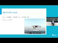
- Symmetrical Airfoil: The top and bottom surfaces are identical, so the camber line coincides with the chord line. These generate no lift at zero angle of attack.
- Asymmetrical Airfoil: Characterized by camber, a curved line midway between the upper and lower surfaces. This camber allows lift generation even at zero angle of attack.
Understanding Camber
- The mean camber line represents the midpoint between the upper and lower surfaces.
- Camber influences lift characteristics, with more camber generally increasing lift at lower angles of attack. This principle can be better understood with further exploration of fluid mechanics in Mechanical Properties of Fluids: A Comprehensive Guide to Bernoulli's Theorem and Applications.
NACA Airfoil Naming Convention
NACA codes describe airfoil geometry succinctly using a series of digits:
- First Digit: Maximum camber as a percentage of chord length (e.g., '4' means 4%).
- Second Digit: Location of maximum camber along the chord from leading edge in tenths of chord (e.g., '4' means 40%).
- Last Two Digits: Maximum thickness as a percentage of chord length (e.g., '12' means 12%).
Example: NACA 2412
- 2 = 2% maximum camber
- 4 = 40% of chord length is where max camber occurs
- 12 = 12% maximum thickness
If the first two digits are zero (e.g., NACA 0012), the airfoil is symmetrical, with zero camber and 12% thickness.
Summary
Understanding airfoil basics, including anatomy, aerodynamic principles, and naming conventions, equips engineers and enthusiasts to analyze aerodynamic performance. The NACA system provides a standardized way to describe airfoil shapes for use in design and analysis.
Thank you for watching this overview of airfoil fundamentals. For more detailed aerodynamics insights, stay tuned!
hello in today's video we're going to talk a little bit about airfoil basics so the basics
that you need to know about airfoils so an airfoil is simply just the cross-sectional shape
of a wing a blade of a propeller rotor or a turbine is simply the cross-sectional area it's not the entire
wing it's just if you took an airplane wing or a propeller wing
and you just sliced it in half and you looked at the cross-sectional area that is what a airfoil is
and this is how the shape of an airfoil determines a lot about how that how that airplane or
the rotor creates lift moves material produces lift has you know induced creates drag
a lot of it has to do with the shape of the airfoil so let's learn some basic terminology
when it comes to an airfoil so the front here so if the air the wind is coming this way
the first part it hits is the leading edge so kind of distinct characteristic of airfoil is this
rounded leading edge it's that it's very rounded and all airfoils you see will have a rounded
leading edge now some like higher performance aircraft that will get thinner and thinner
but for most it's very rounded compared to the trailing edge which is almost always a
kind of a point a sharper point so the trailing edge is the back of the airfoil now there's a couple things
that you then you can break the airfoil down farther so if you draw a straight line like i
did here from the leading edge to the trailing edge this is called
the cord c so that is simply just a straight line between the leading edge and
the trailing edge and then if you want to calculate your angle of attack
which is designated by an alpha that is the angle so let's say we draw an airfoil kind of
at a angle here so it's very steep angle but this is our airfoil
and so our cord line would look something like that and if our wind or air is coming in like
this this angle right here is our angle of attack this is very
large compared to actually as most planes airfoils fly from zero to 15 degrees this is obviously
more than that but just so you could see that this right here is designated as the angle of
attack so i try to draw this one as a symmetric airfoil so the
what symmetric airflow means is that the difference in the size so the the shape is it's a
symmetrical shape it's a symmetric airfoil so there's no camber so the camber line
runs exactly on the cord line now for airfoil like this
which has a weird shape here so this is the top and this is the bottom kind of poorly drawn but as you can see
the chord line which is this first one c h o r d that runs from leading edge to the trailing edge the
chord line is simply the the the middle line it's called like the mean
camber line it's if you took the distance between the top and the bottom so the mine's a little
off because it's very bulbous on the bottom here but if you just took the the different
the area the distance between this the bottom and the top the middle right there is the camber line so this
is how so there's a difference between the cord line and the camber line
for asymmetrical airfoils so this curvature is what gives most airfoils lift
at a zero angle of attack so it can create lift at a zero angle of attack
if it's symmetrical airfoil at zero angle of attack it's not creating any lift because the
pressure differences between the top and the bottom are exactly the same now if you had a
switch gear foil then how did that angle attack it will then create lift so there's a naming
convention for basic airfoils it's called the naca naming convention you'll see a lot of
like a naca let's say 2 4 1 2 or naca 0 0
12. so these are four digit designations for kind of the shape of an airfoil
now what do these mean so the first letter that describes the maximum camber
as a function of the the cord length so just the distance
so the maximum camber as a percentage of the cord length and then the camber is this is the mean
camber line but the camber is the distance between the cord and then the mean
camber line so let's say the if let's say this number was a you know
a four the first digit was a four that means that the camber the large the maximum
camber on that aircraft is where that airflow is four percent of what the cord line is so if the cord was
a meter that the the maximum camber would be uh one four or 100 so four percent so it
would be about four centimeters okay then the second letter or second number
not letter describes distance
that maximum camber is located or where the maximum distance camber is located
so if it's a four and then this is four so if it's like a four that means so this the first letter
is a so if it was a four it'd be a four percent if the second letter is a four that's
forty percent so if a two supposed to be two percent max camber
located at forty percent from the leading edge along the core line
so if it was if against the cord was one meter long core length was one meter
the maximum camber so the maximum distance between the mean camber line and the cord
would be at 40 centimeters from the leading edge so it would be like right here would be for the max
camber is if it was a naca two four one two and then the last two digits
describe the maximum thickness
of the airfoil so no matter where the camber is where the cord
where the cord line is this is and then as a percent so if it's
so if it's a 12 that means the maximum thickness of that wing is 12 percent
of where 12 of the cord so again if our cord is one meter long
the maximum thickness of that air foil is 12 centimeters or 12 percent
over one so the neck is zero zero one two the zeros means well the first zero says
there's no camber so there can't be a location of that camber along the wing so it's
just zero zero and one two it still says the maximum thickness
is a 12 percent of the airflow the cord line it doesn't really tell you the location is located
but it just says the maximum thickness of that airfoil is 12 of the chord line so those are just the
basics of airfoil naming convention characteristics of an airfoil
thanks for watching
An airfoil is the cross-sectional shape of a wing, propeller blade, or rotor slice that determines how lift and drag are generated during flight. Its shape affects the aerodynamic performance; for example, different shapes can optimize lift generation or reduce drag, impacting the efficiency and stability of an aircraft.
Key airfoil parts include the leading edge (the rounded front part meeting airflow first), trailing edge (the sharper rear where airflow exits), chord line (a straight line connecting leading to trailing edge), and angle of attack (the angle between chord line and incoming airflow). Understanding these helps analyze how wings produce lift and react to different flight conditions.
Symmetrical airfoils have identical top and bottom surfaces and produce no lift at zero angle of attack, requiring increased angle to generate lift. Asymmetrical airfoils have cambered (curved) surfaces which enable lift generation even at zero angle of attack, making them more efficient for typical aircraft wings.
Camber, indicated by the mean camber line between the upper and lower surfaces, affects lift characteristics by increasing lift at lower angles of attack. Higher camber generally means the airfoil can generate more lift without needing to tilt as much, improving takeoff and low-speed performance.
A NACA code summarizes airfoil geometry: the first digit is maximum camber as a percentage of chord (2% for '2'), the second digit indicates the position of maximum camber from the leading edge in tenths of chord (40% for '4'), and the last two digits represent maximum thickness as a percentage of chord (12% for '12'). So NACA 2412 means 2% camber at 40% chord length with 12% thickness.
A NACA code starting with '00' indicates a symmetrical airfoil with zero camber and the last two digits denote thickness percentage. For example, NACA 0012 is a symmetrical airfoil with 12% thickness. This type produces no lift at zero angle of attack and is often used in applications requiring balanced aerodynamic behavior.
Grasping airfoil terminology, shapes, and naming conventions like NACA codes allows better analysis and design of aerodynamic components. This knowledge helps optimize performance, predict lift and drag behavior, and create efficient wings or blades tailored to specific flight needs, essential for anyone involved in aerospace design or study.
Heads up!
This summary and transcript were automatically generated using AI with the Free YouTube Transcript Summary Tool by LunaNotes.
Generate a summary for freeRelated Summaries
Comprehensive Guide to NACA Four-Digit Airfoil Geometry and Coding
Explore the geometric fundamentals of NACA four-digit airfoils, focusing on mean camber lines, thickness distribution, and their mathematical representations. Learn how to calculate upper and lower surface coordinates and prepare for coding your own airfoil data program in MATLAB.
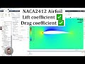
Complete ANSYS Fluent Tutorial: NACA 2412 Airfoil Simulation and Analysis
Learn how to simulate the NACA 2412 airfoil in ANSYS Fluent step-by-step, from geometry creation and meshing to setting boundary conditions and performing flow analysis. This comprehensive guide includes drag and lift coefficient calculations, flow field visualization, and angle of attack effects, making it ideal for engineering students and CFD practitioners.
Comprehensive NACA 2412 Airfoil CFD Tutorial with ANSYS Fluent
This detailed tutorial guides you through modeling, meshing, and simulating a NACA 2412 airfoil using ANSYS Fluent. Learn step-by-step how to create geometry, set mesh parameters, run simulations, and analyze lift and drag coefficients, including the impact of varying angle of attack. Practical tips on y-plus calculation and comparison with experimental data enhance your CFD skills.
Understanding Aircraft Performance: A Comprehensive Overview of Flight Mechanics
This lecture delves into the intricacies of aircraft performance, focusing on flight mechanics, performance diagrams, and the calculations necessary for understanding horizontal flight. Key topics include minimum and maximum airspeed, range, endurance, and the impact of weight on performance.

Understanding Normal Force in High-Speed Vehicles
This video explores the concept of normal force in situations where it does not equal the weight of an object, particularly in high-speed vehicles like sports cars and airplanes. It explains how downforce and lift affect the normal force acting on these vehicles during motion.
Most Viewed Summaries

A Comprehensive Guide to Using Stable Diffusion Forge UI
Explore the Stable Diffusion Forge UI, customizable settings, models, and more to enhance your image generation experience.

Kolonyalismo at Imperyalismo: Ang Kasaysayan ng Pagsakop sa Pilipinas
Tuklasin ang kasaysayan ng kolonyalismo at imperyalismo sa Pilipinas sa pamamagitan ni Ferdinand Magellan.

Mastering Inpainting with Stable Diffusion: Fix Mistakes and Enhance Your Images
Learn to fix mistakes and enhance images with Stable Diffusion's inpainting features effectively.

Pamamaraan at Patakarang Kolonyal ng mga Espanyol sa Pilipinas
Tuklasin ang mga pamamaraan at patakaran ng mga Espanyol sa Pilipinas, at ang epekto nito sa mga Pilipino.

How to Install and Configure Forge: A New Stable Diffusion Web UI
Learn to install and configure the new Forge web UI for Stable Diffusion, with tips on models and settings.

If you found this summary useful, consider buying us a coffee. It would help us a lot!