Understanding Aircraft Performance: A Comprehensive Overview of Flight Mechanics
Introduction
- Welcome to the first live lecture on flight performance and mechanics.
- The focus is on creating performance diagrams for different aircraft types using Excel.
Performance Diagrams
- Two types of performance diagrams: force version for jet aircraft and power version for propeller aircraft.
- Calculations include lift coefficient, drag coefficient, and required power based on airspeed.
Horizontal Flight
- Main topic: horizontal flight and its mission profile, including takeoff, climb, cruise, and descent.
- Discusses steady flight conditions and the importance of airspeed in cruising flight.
Key Airspeeds
- Minimum Airspeed: Achieved at maximum lift coefficient.
- Maximum Airspeed: Found where available power meets required power.
- Maximum Range: Distance covered per kilogram of fuel.
- Maximum Endurance: Time spent in the air with a given fuel load.
Equations of Motion
- Simplified equations for symmetric flight conditions.
- Focus on thrust and drag relationships to determine performance metrics.
Propeller Aircraft Focus
- Example: Spirit of St. Louis, with detailed drag polar and engine specifications.
- Performance diagrams show close alignment with real-world data.
Calculating Airspeeds
- Minimum airspeed derived from lift equations.
- Maximum airspeed determined through power equations and drag relationships.
Range and Endurance
- Range defined as distance per kilogram of fuel; endurance as time in the air.
- Specific range calculated using velocity and fuel flow.
- Emphasis on minimizing drag for maximum range and minimizing power for maximum endurance.
Conclusion
- The lecture concludes with a summary of key calculations and the importance of understanding performance diagrams for aircraft operation. For a deeper understanding of the principles behind motion, you may find Understanding Motion: A Comprehensive Guide helpful.
- Homework assigned to practice calculations for a different aircraft model, which can be complemented by insights from Understanding Motion: A Comprehensive Guide for Class 9 Science.
okay ladies and Gentlemen please take your seats okay uh welcome to this uh first
live lecture let me first tune the volume of the audio is it clear to you or is it too loud not loud enough yeah
okay that's fine now yeah oh I was here in a spot where had no reception anyhow interesting uh yeah I've never done
military service I've never been a drill sergeant so my voice is not that loud um anyhow Let's uh let's get back
to uh to flight performance flight mechanics aircraft performance whatever you like to call this um I gave you a
bit of a challenge to make a performance diagram for for this aircraft uh and also the uh the next one uh which is on
the next slide um I'll show you how I did things uh uh I used uh I used Excel uh for this
uh and what what I did maybe I need to dim the light a little bit then becomes a bit more
clear uh basically here I have here I have the the data for the first aircraft and here I have the data for the other
aircraft and then I just started making a table I started with the velocity and the thrust had been given for this jet
aircraft is 12,000 Newton and then I just started calculating a lift coefficient drag coefficient and then
the drag itself and I plotted that for a whole series of of air speeds
uh and then I could make a a graph like uh like this uh so this is the force version of the uh the performance
diagram and I did the same for the uh the other aircraft the propella aircraft uh but in that case this was my set of
data and for a propeller aircraft we normally use the power version of the uh the performance diagram so I need to
talk power available power required power so that's what I did as well I had the available power being
given I calculated based on my air speed and the weight the lift coefficient drag coefficient drag and I multiply the drag
with the velocity to find required power and then the performance diagram looks like looks like
this if you look a little bit in the numbers for instance for this diagram you would see the point where the
available power meet meets the uh required power would be at the speed of more than 300 met per second that's
totally insane this will not happen for this aircraft but just to give you a bit of a feeling on how this this would work
who have you tried this as well at home uh a couple couple not bad not bad um someone before starting the
course asked me uh do I need to do this on the exam well maybe maybe not in this case I always say I am not at the
Liberty to speak or if I tell you I have to kill you like they say in the military so I'm not going to tell you uh
but maybe I'm going to ask this maybe not so I don't know yet because I haven't made exam questions yet
um okay let's go to the let's go to the uh the second lecture the second lecture is going to
talk about horizontal flight so the main topic of today is horizontal
flight um and before we discuss this I first need to talk about a typical mission of aircraft a So-Cal Mission
profile we will detail that later in the second semester in the course on aircraft design but here I'm going to
give you the basic Mission profile and it starts all by a takeoff and a climb then you climb to a certain what
we call Cruise altitude uh and at that altitude we perform the cruising flight in this second year will tell you
that the cruise flight is normally not a straight and level Cruise flight at one and the same altitude for many hours
uh if you want to optimize this you go up a tiny bit why do you go up well because after a while you have burned a
certain amount of fuel your air has become lighter then it becomes easier to fly a bit higher and the higher you fly
the lower the density the less drag you have so normally you go up in a cruising flight but for this course we'll say uh
horizontal cruising flight and then at the end of the flight you descend and then your land your
aircraft but today I'm going to talk about this uh this cruising flight how are we going to do
this well we're going to look into a number of interesting air speeds in this cruising flight actually four points of
interest the first one is at the lower end of the speed envelope the minimum air speed uh
another one that's of interest is the maximum air speed uh and then two more interesting ones is maximum range how
far can I fly how do I need to fly if I want to maximize my range and the last one is called maximum
endurance that means how long will I stay be able to stay in the air for a given amount of fuel I have taken on
board um for that we need to First Define flight
conditions and this course we're going to talk about a steady flight condition now and that means a flight in which the
forces at moments acting on the aircraft do not vary in time neither in magnitude nor in
Direction so in our equation of motion we will say in a minute dvdt equals zero um it's going to be a horizontal flight
and that means the aircraft means at a constant altitude that means that the air path angle GMA is going to be
zero and then and that's an assumption we have for all the cases we're going to analyze this course it's going to be
symmetric flight so for now you can forget about that but flight is symmetric that means both the side slip
angle is zero uh and the plane of symmetry is perpendicular to the Earth so side slip
angle beta is zero and the aircraft is not turning but that's for all Maneuvers
we're going to discuss in this slide so the important thing for now is going to be steady dvdt equals z and GMA equals z
it's going to be horizontal flight now let's go back to the equations of motion for the symmetric
flight these were the equations of motion U and we're going to simplify them
and actually I think you already have seen the outcome of the simplification uh but I'll do this step by step what
we're going to say looking into this uh equation we're going to say dvdt equals zero so this term is going
to disappear furthermore we're going to say airpath angle in horizontal flight is
zero so that means s of GMA equals zero and cosine of gamma is going to equal one and since gamma is zero it's also
constant and that means also D GMA DT is going to be zero for this
flight and then for now I'm going to make one more simplification and I'm going to say the thrust Vector is going
to be aligned with the air speed vector and that would mean that my Alpha
T is going to be zero so this is going to be T and here s Alpha is going to be zero so this term is going to disappear
so what we will see in a minute for horizontal symmetric flight cine of alpha T is 1 s Alpha T is zero s of GMA
is going to disappear D GMA DT is going to disappear and dvdt is going to disappear and then surprise surprise
this is what is remaining of the equations of motion very straightforward you will be surprised
how much you can do with these two simple equations so that's the uh the starting
point um now what I am interested in is this aircraft for this aircraft I'm going to
make some calculations and you clearly recognize this as a propeller aircraft uh so in this lecture I'm going to focus
on propeller aircraft on brid space I'll post an a little document where the derivations are being done for jet
aircraft because we do Jet and we do propeller aircraft this lecture going to focus on propeller aircraft it's very
interesting aircraft very very long range uh aircraft Spirit of St Louis was the first across the the Atlantic
Charles Lindberg was the the person behind this uh it now seems so seems so obvious uh because you just book a
flight and you got gr literally everywhere nonstop well in those days uh several people tried and many died in
the course of doing so Charles lber was the first one who was was successful yeah those were the pioneers
of Aviation uh uh also one of the R Brothers died in I think in an aircraft crash uh so I would always say don't try
this at home uh but the interesting thing for this this aircraft is it has been
extremely well documented uh and we have the full drag poar and you recognize now we have a two-term drag
poar we have cdal cd0 plus K1 CL plus K2 CL 2 so K1 is minus
0880 and K2 is1 169 and for this aircraft there's also a maximum lift coefficient
uh and we have engine power that we're going to use 236 horsepower 1800 RPM revolutions per minute by the way uh
and the wing surface area is 29.7 square met so that's going to be the input
here um now I can make a performance diagram for this aircraft that's exactly what I did for the for thepooter and the
other aircraft so I can make a performance diagram and that would look uh look like
this and the interesting thing is that based on culations the Excel file uh you can see
that it is very close to reality this was the uh the NAA report which analyzed this this aircraft and you can see the
the flight test data which are the the blue squares the match is really astonishing by just a very simple
calculation with this two term drag polar you get very very close to reality it's a very good system uh
okay um now we're interested in a couple of of points if I put the engine power in here uh then I also have the full
performance diagram the red line here you could also estimate what's going to be the maximum speed but I'll talk about
that in a second and what I'm going to do now is to find minimum and maximum air speed
I'm going to talk about range I'm going to talk about endurance when I have time today I'm going to talk about thing
called speed stability then a summary but maybe that's for for for Thursday's lecture so minimum and maximum air
speed um this is the starting point propeller aircraft steady horizontal sutic flight
lift equals weight thrust equals the drag and then well it's pretty straightforward to find minimum air
speed I will do this in a couple of steps on the uh let me see
what I'm going to do now the probably it's best to go to uh
pc1 for those who are in the the lecture room it's handier to have all the qu screens but for the ones at home it gets
very tiny on their screen so I'm going to use in a couple of larger steps I'm going to use the uh the screen
here um I don't know whether it's readable here but you can anyhow see this this screen so we're going to talk
about minimum air speed oh that's very big I'm in another
screen I need to go into number one yes so the first thing I want to look
into is minimum error speed and what I know from minimum air speed my lift coefficient is going to
be the maximum lift coefficient you know that of course when you want to fly slow you fly at maximum angle of attack at
the maximum lift coefficient and now use the equations of motion
uh equations of motion we have thrust equals and lift equals
weight and this is the interesting one because this we can write as CL half Row v^ 2
s and by the way unless specifically told otherwise I use true air speed I don't talk equivalent air speed or
indicated air speed I talk through air speed normally equals the
weight and from that I can figure out that the velocity
equals W / S 2 over Row 1 over CL and from that the square root and since we're flying
minimum air speed I have maximum lift coefficient so find finding out the minimum air
speed of an aircraft is pretty straightforward just use the
this equation of motion in this form and this is also a great tip for for the exam sometimes
people uh Panic a little bit because they don't figure out how the things work they don't understand anymore if
you just remember this equation in this format you normally get started pretty quickly
yeah I'll show you that a couple of times but if you don't know anything anymore this might might get you started
but effectively you're solving one of the equations of
motion so that helps normally um
okay we now know minimum air speed so that's an uh an easy one uh if you want to know what is the drag
then or the power uh well you can just the power required is of course the drag times
velocity and the drag is CD time half Row v^ 2 s times velocity so you have to figure out
CD half Row V cub and then you have the drag of the aircraft and then you can plot that in
your performance diagram sure you have the power the power required you can put that in the
performance diagram and then here I have the power here I have
velocity then you have one point in your diagram and in the end we'll see that the curve starts developing
like that okay one thing done let's move on to the next one let's look into maximum air
speed ah that used to work yeah it did work in the past maximum air speed maximum air speed
what we're looking for now is the following po here we have the available power here
we have the required power and here we have velocity and here we had the minimum air speed so we're now
interested in this specific pointer if you have uh the data of this aircraft if you have drawn or you have
measured the uh the curves the power required and the power available you can just put it in a graph and read it there
but we can also see how far we get in in an analytical approach here now um we have the equations of
motion tals D and lift equals the weight or equivalent from that that the available power equals the required
power and we talk about propeller aircraft it helps to talk um Powers the maximum air speed we find at
the point where the maximum available power matches the required power so this is Pa and actually the maximum available
power okay now we know that and that is just a number so we're going to say b a
Max equals the required power equals the drag times the velocity and now I'm going to going to
do a little trick that we're going to do very very often in this course it's a very simple one I'm just going to
multiply this by One D * 1 * V why multiply this by one well because you can write one in a
different way as well D times the lift over the lift there's nothing wrong with that
mathematically perfectly sound but then I can take the next step I can say that is the
drag over the lift multiplied by the lift multiplied by the velocity and then I can take the next
step I can use the other equation of motion and then I can
say I'm going to move this a little bit further I'm going to use that for this term I'm going to say then this is
the drag over the lift multiplied by the weight multiplied by velocity so I have now gotten rid of one
of the unknown which is the lift for us and I'm assuming that I have a given weight now I'm going to raise this and
this is a extremely slow process uh I can also scroll down a little bit but that uh
takes and then I'm going to take the next step I'm going to write this as
CD half Row v^ 2 s over CL half Row v^ 2 stimes the weight times times
velocity which then becomes CD over CL times the weight times
velocity why would I do that well I'll show you in a
second uh but this is a way that we're going to use multiple times because we know something about CL and CD we know
CL CD via the Dr poar the lift Dr poar and that is what I'm going to use now and why I'm going to do this well
because because the velocity is a function of
Cl remember we had l equals weight gave me velocity equals w/ S 2 over row 1/ C so for a given aircraft given weight
and given surface area and a given altitude the velocity is a function of Cl but also
CD is a function of Cl via the lift Dr polar and what I have done then is that I have made something here which is only
depending on one variable only depending on the lift coefficient and when I have one equation
with one unknown I can solve it because that's the trick we need to go to a situation where one equation one unknown
let me see where this wants to scroll up no it doesn't then I have to go to the next
slide now I furthermore know that CD equals CD 0 plus K1 *
cl+ K2 * CL 2 I will assume furthermore weight is
constant and the density is constant because I'm flying at one and the same altitude I'm in cruising flight
so density doesn't change if I'm looking at one moment in time so I forget the fact that we burn fuel we talk about
range and endurance I'm going to burn fuel and then we cannot assume that uh later so we have only one variable
remaining now just uh plug this in ba Max
equals CD c which is cd0 plus K1 C + K2 CL 2 over CL
multiplied by the weight multiplied by the velocity which is W over S 2 over Row 1 over
CL um what is now handy is to put everything into one big square
root so what I can do is now C d0 + K1 cl+ K2 CL
2 over CL squar squar L big uh square root w^ 2
times w/ S 2 over Row 1 over CL which then is
cd0 plus K1 cl+ K2 CL 2 over CL squared and this also
squared play a little bit with the other things what I will figure out is that I have weight cubed over s * 2 for
row let me see if I don't know any mistakes and then I can find the following solution I
can find cd0 plus K1 cl+ K2 CL
squar this squared and C L cubed and I have to have the CDL cubed
here as well equals p a
Max squar * s over weight cubed time row over
two and the principle you could solve this for cl and then you can figure out the air speed I will not ask you to do
this in the exam at least not to solve this fourth order equation uh but if you do that with a graphical calculator you
can figure out what the CL is there's one catch here there's one catch
here and the catch is the following if I have my performance diagram I have here my required power
and here I have my my a Max what I'm interested in is the
maximum air speed so when I solve this I will find this
pointer but I will also find another pointer I will also find mathematically speaking
I will find a second solution and that is of course a useless solution because
this was the minimum air speed so this is physically not possible so the boundary condition is
that CL must be large smaller smaller than CL Max so mathematic Al you will find two
solutions physically you can only find one solution so that's the catch in there okay
that's I've also put that uh in the slides I'll run through the slid in a second everyone write finish writing
uh yeah more or less uh okay um well for this aircraft this is the data
that I've been using uh so the numerical example and then I could find a minimum air speed of 114 km per
hour but what you also see that in fact this is weight dependent so I first made the calculation for the maximum
weight but also I have been given here the the minimum weight and if I plug it in for minimum weight you see that the
aircraft can slow down much further so when you have a lighter aircraft you can fly slower so throughout the flight
Charles Lindberg had to change his uh his air speed as well uh can you even go slower yes of
course you can go slower uh I guess you have been told about flaps and slats is that
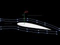
correct no okay then I'll tell you uh um you know about in aerodynamics uh it helps to have some curvature in the the
the air foila because then you can deflect the air further down and thereby according to Newton's third law have an
equal opposite and colinear reaction upward Direction which is called lift um and that's what people do by
changing the curvature of the air fors by what they call so-called flaps they can be very simple this is called a
plain flap this thing is called a split flap and the more interesting it becomes is
you had an Gap there and this Gap is there because the flow over the top surface of the air foil uh gets gets a
bit tired so to say you get all kind of uh separation maybe uh well n Timmer told you all about this
uh and what you can do by and this air re-energize the boundary layer because
here you see there's a boundary layer developing uh and by putting new energy into the boundary layer the flow will
not not separate but it will be able to follow the Contour of the air from much further and thereby push the air more
down and thereby get more lift so that's a trick of an of a split of an of an uh of a slot here and this
is what we call a single slotted FL FL you can also add more slots here you have a so-called double slotted flap
there's one slot over here and a second slot over there so you can do the trick another
time you also have a thing called a Fowler flap that does do not hinge but it also extends a bit of so it not only
increases the curvature of an airfall but it also increases the surface area of the wing so more Wing
area um you can also do things in the Leading Edge then they call it a sled although this one when it comes out is
called a Krueger flap the Boeing 747 had Krueger flaps uh you can drop the Leading Edge or you can even have a a
slot here uh and if you look into a large aircraft very nice example Boeing 747 that has a triple slotted
flap and a triple slotted F flip and here you see the first slot here's the first part of the flap then
here hiding by there's the second slot and the second part of the flap and then here's the third one with a third slot
and this has a a kruer flap that folds out out of the Leading Edge to increase the
lift and these are massive devices and they're also pretty heavy and they're also sensitive for maintenance and you
still carry them along you only need them a couple of minutes every flight but you carry them along for many many
hours so what the more or less modern uh development is is to go to single slotted fer flaps a bit larger so the
A380 had a very large but only single slotted fer flap uh on the airf frame okay uh that we spoke about the
minimum air speed we know now uh what that was I want to tell the pilot U um for the maximum air speed uh we can
calculate things roughly 55 m/ second is the the answer for this aircraft and also again from
the flight test data you can see that with this very simple approximation with the lift drag polar you can get very
very closer um now spoken minimum air speed and we have spoke about maximum air
speed and then the next topic is going to be range and that means how far can I go with the aircraft but let me first
check here are there burning questions from the people online no okay so they have fallen all asleep
uh or they're still very up to date let's talk about uh range range
what does it mean range how would you figure out yeah yes range is about distance and
that's very important with a given amount of fuel we want to cover a certain
distance so when I burn fuel when I burn a kilo of fuel I want to maximize the amount of meters I travel so a measure
for range is the meters per kilo of fuel so I want to figure out something a
parameter that gives me the meters I cover per kilo of fuel keep that in mind so range so what I'm going to use is a
thing called a parameter called specific range here
and the parameter for that is velocity over a Thing Called capital
F and that capital F is not the force it's the fuel flow so
F fuel flow and if I look into the units of this I have here m/
second and the fuel flow is kilos of fuel per second and I worked it out I have my
meters per kilogram so by looking at this parameter I have a very good parameter for
calculating the range of the aircraft by just looking at this specific a specific range parameter so is the
distance it is the distance covered per kilogram of
fuel distance covered per kilometer of fuel and I need to optimize this so I need to of
course some way to find to optimize this okay now we learn about velocity question uh you could do that uh the
question is if f is a mass flow should you little put a little point about that um quite often instead of f we use m.f
the mass flow fuel but in AC performance we do a couple of other things every now and then we have
also weird coordinate systems uh so I reserve the right to do other things uh uh fuel flow I need to optimize this
well let's talk about this fuel flow first this is by definition a specific fuel consumption
times the brake horsepower the or the shaft power you could call this where CP is not a pressure coefficient it's
specific fuel consumption and is the brake
horsepower or shaft power okay but this is not going to help us we need to do an up a couple of other
tricks here suppose I have my engine here and on that Ang there's a propeller
there and this engine gives me and then in the end I have available power and in between
there there is the propulsive efficiency so what I have the available power equals the efficient propos
efficient times the shaft horsepower sir plugging that into the
equation I get my fuel flow equals my specific fuel consumption multiplied by the available power over
the propulsive efficiency um and now we have to make an assumption
actually have to make two assumptions the first assumption is that in Cruise flight uh the engine performs more or
less normally and we can say that the specific fuel consumption is more or less a constant
ter and also for the propulsive efficiency for the propeller efficiency in case of a propeller engine we can
also say that the propeller efficiency is constant remember we had this uh this
efficiency curves velocity efficiency they were a bit depending on air
speed but depending on the pitch angle of the blades we could say okay we can more or less make this a
constant so we assume a adjustable pitch propeller actually constant speed propeller uh is for called and there we
assume constant so when we have this we can plug that into our equation so combining
everything V over f equals
V over CP over EA J * D * V equals at J over CP
times D because the available power is drag times velocity because it's exactly the
required power at the moment we fly why is that
because because one of the equations of motion tells me thrust equals a Dr or
available power is required power so that I have now implemented in
this this equation um I'm going to save this because we might need
that so that I'm going to uh PC2 right and the interesting thing is this this Beamer has four computers inside so
I can play with that a little bit uh but I have to keep do have to do some bookkeeping to keep it going anyhow um
okay we now assume okay let's let's rear this V over f equals EA J over CP *
D and we had assumed assumed andj and CP are constant then I can
say that this is equivalent to 1 / D the ratio is equivalent is proportional to 1/ D this when I want
to maximize range that means V over F The Meters I travel per kilo
fuel maximize leads me to one over D to be
maximized which leads me to the point where the drag is minimized so if I want to fly maximum range I need
to fly at the air speed where the drag is minimized sounds like a normal
conclusion eh it's not weird it's not weird okay um to put this in the performance
diagram now let's me let me do this here so actually I need to draw two performance
diagrams here I have the power version of the performance diagram and here I have the thrust
version of the diagram what I'm now seeing is that the
tangent the angle of the tangent here is proportional to 1 over V over F and
then this is the point where I find the maximum or the optimum performance and if I translate that into
the force version of the performance diagram I have here the point where I have minimum drag and here
I have the Velocity that belongs to this okay and after the break I will show you how to calculate those values
so stay tuned for the next episode in 15 minutes from now
okay while the last ones take their seats I have one question specifically for the the students joining us uh from
home uh um could you please in the chat comment whether the screen as you see it now with the four quadrants visible
whether that is still readable for you uh because it gives a bit better overview those uh here in the the
lecture room but I want to know whether this is still readable uh for you uh so then my uh two lovely Tas here will
follow the chat uh and uh I don't know how it looks with their screen uh there's a bit of delay so yeah of course
there there of course there some delay so so when you if you comment this in the chat I will continue
on the uh on the large screen but now you have been able to see this
okay let's go uh let's go back where we were okay so it's a bit mixed mixed okay then we keep it like this
uh okay let's go back um we figured out now that for finding the point of maximum range we need to
fly at the point where the drag is minimal so in the force version of the performance diagram is the bottom of the
graph over here in the power version of the diagram it's the point where you touch
the graph so here we have the drag curve and here we have the power required curve okay okay now just tell the pilot
fly minimum drag and then the pilot will tell you I don't know how to fly minimum drag I do
not have a drag meter on board in my cockpit there is no such thing as a drag meter okay can't we make a drag meter
then probably we could but there is a much more elegant way to do this uh and I'm going to show you the more elegant
way so that even Pilots can understand this uh
okay the trick drag I'm going to again apply my little
trick by multiplying the drag by one mathematically totally sound nothing wrong with
that and then I'm going to replace that by lift over lift and then I'm going to
say remember my equation of motion and then I'm going to say is D over
L the weight or equals CD over CL times the weight
now if I want to fly at minimum drag minimum
drag I need to minimize this and I'm going to say we look at One
Moment In Time and th we can say the weight is constant in this one moment in time I'll
come back to that later because the weight will change uh so the answer we find here is not conclusive but for the
time being I will say this one moment in time and that means that we can
say minimum equals CD over CL minimum multiplied by the
weight so if you want to fly maximum range you need to fly at a lift to direct ratio you need
to fly at thus we need to fly CD over CL
minimum or of course equivalent CL Over CD maximum and we'll use that quite a
couple of times when the mathematics initially tell us to minimize something we can convert that into maximizing the
opposite uh there so this is what we need to
do let's go to the next screen um let me see which one I have not used I have not used number four it
is let's go to pc4 before um okay what I must do I must either just
minimize or maximize the values so what I'm going to do I'm going to
say mathematically now let's create a little bit more space
mathematically I'm going to do the following I'm going to take the derivative with respect to my
independent variable CL going to take the derivative of CD over CL and I'm going to equate that to zero
that's the same as as optimizing take the derivative and equ that to zero you could
also take this CL CD with respect to uh
CL that will be the same and we will play a little bit with that uh we'll play a little bit uh with that what is
the the best uh the best option but in this case it's handier to play with that but you can do exactly the same and a
couple times I will show you the opposite uh to show that it's the same okay now how are we're going to do
that well by just filling in what we know I'm going to take the derivative of CD well CD is
cd0 plus K1 CL plus K2 CL squ over CL
with respect to my independent variable CL which is the derivative
of cd0 over CL
plus K1 plus K2 * CL with respect to
CL I'm just filling in what I know I don't do any mathematical tricks yet I'm just filling in what I
know and then I'm going to take the derivative which is
minus cd0 over CL 2 that's the derivative of cd0 over
CL the derivative of K1 with respect to C is zero plus the derivative of K2 CL with
respect to CL is K2 and that must be equal to
zero so the equation I find minus CD 0 over CL squar plus K2 =
0 and from that I find that the cl value equals
cd0 over K2 and this is then the optimum
so if I fly at the C CL value which is equal to the square root out of cd0 over K2 then I fly for maximum
range okay come to your question in a second what do I tell the pilot well please fly at CL
equals this value and then the pilot says I don't have a drag meter and I don't have a CL meter so what to do next
who has the answer use the air speed yes yes use the equation of motion use the equation of
motion lift equals weight and thereby V equal W / S 2 over Row 1 /
CL so I can find the optimum value for the air speech and this is what they can tell the pilot because the pilot
does have an air speed indicator does that answer your question also or not oh
well maximum that's enough that's mathematically enough for what we need
to know because there is one Optimum only or at least there's one realistic
Optimum only uh in this that that makes this score so easy uh uh sometimes you do have trouble with
that but but you can see based on the numbers whether it's correct or not well I'll get back to that
later yes by yeah maybe you remember what I did in the previous hour when you find the
found the maximum air speed one was nonsense and the other one was correct uh you need some physical background you
need some Aerospace knowledge to judge which is mathematically the best solution and that's why you can
choose at your convenience to do this this or this because you do have some background
knowledge by now you have been here for a couple of weeks now so you have enough knowledge to make that engineering
judgment so the this is how it uh how it works and this is what we can tell the pilot uh now let's go back to the uh to
the slides um should lower it a little a little
bit okay what do we know I think I need to dim the lights a little
bit and this is not an invitation to fall asleep of course uh um now for the Spirit of St Louis uh
this was the uh the data we had so far and then of course the the the key point was what to tell the pilot yeah minimum
aerodynamic drag well we now know that this is what we need to do we need to take the derivative find an Optimum CL
value and then translate that with my equation of motion into the uh the flight velocity that he or she can see
on the air speed indicator um and you can find that in the performance diagram I showed you you
need to look at the tangent to this curve which is the bottom on this curve the force version and a power version of
the performance diagram so the tangent there um in
principle you could figure out what is your range or your specific range V over f for any point in the curve by looking
at the the yeah the angle of this point this line should be up a tiny bit further but the angle of this curve here
determines my specific range and where this angle is minimized where is tangent you find the maximum
performance um now here's some data I've just solved my equations the optimum air speed with the
optimum lift coefficient this was the optimum lift coefficient plugging in my numbers uh with this this aircraft
data and I found my lift coefficient I find my Optimum air speed in this case 3045 m m/ second about 100
km per hour but you also see that in this equation you have the
weight so there is a weight dependency in this so this is what we figured out
uh um now if you want to put in the numbers uh here's some more data for this aircraft we
estimated the propeller efficiency to be 75 and the specific spefic fuel consumption 6.45 10 the^ minus 8 when
you look in specific fuel consumption you always find a very very tiny number 10 the^ minus 7 10^ minus 8 this is not
a large number it's a very small number and why is that well because aircraft are so bloody efficient they only use a
very little amount of fuel it's still too much for sustainability purposes but it's very very efficient and the unit in
this case is kilos per wat second and this is CP this is for propeller engines
specific fuel consern Propel engines if you look at the jet engine people normally use a CT t for Thruster and
then the unit changes a little bit because then you have to do with forces instead of with powers so look carefully
at the units but in this case 6.45 10 to the power minus 8 and then you can calculate the specific range and from
flight test data you can see that it's pretty close uh so only a 4% difference and for a fuel consumption this is very
good this is pretty accurate uh knowing the the little amount of knowledge we have so far what does this number tell
me Well actually it tells me that the aircraft can fly a little more than 8,000 M more than 8 kilm on one kilo of
fuel and this is a very old aircraft nowadays this is much much more efficient
uh um there is an effect of weight because we lose wait um if I
move through the flight I can see that my performance diagrams start changing at least the power requirement curve
changes and in this case I have made some some drawings here uh for the the black
one is for minimum weight the red one is for medium weight and the blue one is for maximum weight and you see if you
want draw the tangent and I think I've done that you see that the optimum point from high weight to low weight
changes so throughout the flight Charles Lindberg needed to fly slower and slower and slower he started at let's say
around 45 m/s and he ended a little over 30 m/ second so the moment the flight progressed it
took longer and longer and longer to cover a kilometer but the aircraft becomes more fuel efficient of course
because it weighs less so here you see the tangent lines you had to draw for
that um as the homework I'll give you this uh this aircraft DC3 propeller aircraft
uh I have some data for that specific fuel consumption prop efficiency available power Mass stall
speed Etc so I want you to draw the performance diagram power version of the performance diagram I want you to find
the CL Max and the maximum air speed and I want you to calculate the maximum V over F what is the maximum specific
range for this aircraft I post the slides after the lecture so you can uh can see that and work on that for
Thursday's lecture um next one let me see oh yeah I have enough time next one is
endurance endurance tells me how long can I stay in the air how many minutes or hours can I stay in the air and of
course we want to optimize that so what we're going to do here is look into for a given amount of
fuel how long can I fly with that amount of fuel so it's now more time related than instead of distance
related so let's go to the uh screens again um I'm going to uh PC2 okay I have a clean sheet of
paper give you a little bit more light endurance yeah for that we need to look at the
fuel flow because I want the fuel to flow as slowly as possible to minimize the
amount of fuel I need per per second per hour per day or whatever so I look at the fuel flow
f equals of course in units kilos per second so I want to have the fuel flowing as slowly as possible
possible and F we we remember was CP times the shaft horsepower or the brake
horsepower or what we did CP times p a over propeller efficiency which was also CP times the
required power over e j because my equation of motion for horizontal
steady flight told me that thrust equals direct or the available power is equal to the
required power now again I'm going to assume that my specific fuel consumption
CP and my propeller efficiency are constant there I assumed that to be
constant and that means that for eax and not f but f e stands for endurance if I maximize my
endurance I need to minimize minimize my required power and that feels logic H if you
minimize your power you consume less and you can stay in the air as long as possible so that makes sense
okay now the easy one is if you have a performance diagram a power
version then you find the lowest point minimum required power and then you just read it from the graph
and you know what you need to do so you can tell the pilot also how fast the your she needs to
fly but of course I want to have an analytical solution as well so I'm going to give you as analytical solution as
well and that comes as follows the required power minimized
equals D * V that the product of drag and velocity needs to be
minimized I cannot say that I need to minimize the drag because it drag times velocity there the product that needs to
be minimized we have to be careful with that okay let's do my little trick again I'm
I'm going to multiply this by one and write one as lift over lift and then I'm going to say one of my equations of
motion is lift equals to weight so I can immediately convert this into CD over CL times the weight times the
velocity and for the velocity we know W / S 2 over Row 1 over CL so effectively I
have now applied lift equals weight twice one time they get the weight here and one time to write the air speed in
another way but that equation is valid because that's one of the two equations of motion we have in this case of
horizontal steady flight or this gives me in total W
cubed / s * 2 over row Time CD squared over
CL cubed and of course that needs to be minimized
now assume we're flying at One Moment In Time that means the weight we can momentarily take as a constant we flying
horizontal steady flying so the density is constant we're not extending R ring flaps or so so the S is constant so this
leads to that we need to do the following CD squared over CL
Cube to be minimized or equivalent CL cubed Over
CD squared maximize and it's a matter of
convenience to to choose here and I'll show you what to choose but you can do it either way um you have to be a bit
flexible mathematically yeah um what I'm going to do I'm going to to do
this why because it has proven to be M more convenient but I can also do it the other way around but this is what I'm
going to do so let's go to my next screen so what I'm going to
do I'm going to to say CL cubed Over CD S I need to uh to
maximize well how do I do that take the derivative with respect to the independent variable and equate that to
zero what is my independent variable well that is the lift lift coefficient because CD equals CD 0 + K1 CL + K2 CL 2
is a function of Cl so what I need to
do I need to take the derivative of Cl cubed Over CD s with respect to my independent variable
CL and equate that to zero that's what I need to do mathematically again you can also take
the other form it's a bit more involved but you'll find the same answer in the end um
okay if you think this looks a bit difficult sometimes it helps to say well CL
= X and CD equals y and then you need to uh find the uh do the same thing but with X and Y sometimes it works handier
but I use the uh the way we use it here okay um you have to be careful here because
here there's no easy way to write it uh uh like we did in the previous example so you need to apply a quotient ruer so
apply the quotient rule apply the quotient rule how do I do that well I get I'm just now taking the
derivative of this term with respect to CL what do I have I have the denominator CD squ multiplied
by 3 CL 2 minus CL cubed * 2
CD and now be careful multiplied by D CD D CL you need to apply product rule as
well divided by uh CD to the power 4 and that must equal
zero and quite often I see that people have the tendency to forget this term but I take
the derivative of CD 2 which is 2 * CD but CD is a function of Cl so you need to apply the product rule so you need to
take this term into account so this is coming from the product rule okay
H this looks pretty complicated but there is a rather elegant solution but that requires some
aeronautical Insight when is this expression zero say again yeah if the denominator is
zero under the condition that the denominator is never zero otherwise you get zero over zero and
that is nonsense okay that would solve our problem but can we be absolutely
sure that this is never zero yeah B it's it's cubed so it's never
going to be negative of not cubed is it's to the power four it's never going to be
negative uh but I have not seen a flying aircraft which has no drag if you see that call me just in the
middle of the night or whatever call me because then together of us we're going to be rich very rich so cd0 is never
going to be zero because there's always something even if C you will never find an aircraft with
zero drag well you need to go very far out of space where there's no atmosphere left anymore then maybe okay but if you
do call me huh expain yeah because the question is why
did I apply the product role because what I'm doing here for the second term I take the
nominator multiply by the derivative of the denominator and the derivative of CD ^ 2 is 2 *
CD but I'm doing the derivation with respect to CL and I know CD is still a function of Cl so
that's why I need to include the product rule so don't forget that if you do that so we can
say CD to the^ 4 is zero and if you find something you call me um and that that means that we can
simplify things oh other the way around so
does I need to figure out CD squar * 3 CL 2 - c c l cubed time 2 CD D CD D
CL equals zero okay um cleaning up things a little
bit CD 3 CD squar CL s equals 2 CL
cubed CD D CD DCL so I've moved that one to the right hand side of the equal
sign um can I simplify things yes I can simplify a couple of things I have a CD here and here so I can get rid of one of
the CD terms I have a CL squared here and I have a CL cubed here so I can get rid of
this so that simplifies to
3 CD equals 2 CL D
CD DCL and then I'm going to use this term and I'm going to write DCd
DCL equals nothing from cd0 K1 from CL K1 + 2
K2 CL so I've now take the derivative of CD with respect to the independent variable
CL that leads me to um 3 over two I'm going to move the two to the other
side um times
CD over CL equals K1 + 2 K2 * CL and I'm looking for the CL value I need
to fly it but I still have one term CD which is a function of Cl so I need to fill in my lift drag polar once
more so which is equivalent to 3 over 2 times CD is Z Plus K1 * CL + K2 CL
squar over CL equals K1 + 2 K2 * CL and then the next step
is to move this C over here and for that I'll wait a second till youve been able to copy that down uh
that gives me the opportunity to take some sip of cold tea okay I'm going to move on uh a
second computer number four um where do I stand so what I have I
I have three * cd0 plus K1 * CL + K2 CL
SAR equals 2 K1 * CL plus 4 K2 * CL 2 um I can now group anything group
everything uh uh order terms so I get um CL squared multiplied by
3 K2 Min - 4 K2 plus I get terms related to CL that
is 3 K1 minus 2 K1 plus 3 * cd0 equal
0 oh what did I do to go back I was too optimistic grouping things so I get
minus K2 CL squared plus K1 CL + 3 CD 0 equals
0 and this is a second order equation in CL recognize ax2 + BX + C = 0 and we know
that we have the square root formula to solve that uh square root formula square root
formula then I get CL 1 comma 2 I will find two solutions here and you will need to apply some
engineering judgment to see which one is the correct one um but that is normally pretty
straightforward if I apply the square root formula minus K1 plus or minus square root
of K1 2ar plus 12 K2
cd0 over minus 2 K2 or that is equivalent to K1 in this case I've just taken away the
minus sign uh here and here and formally for me then I need to right here minus and plus but I don't care
about that uh that gives me two solutions uh and those two solutions you just have
to calculate them both and then you have to apply some engineering judgment on to see which one makes sense and which one
makes no sense and very often you will find someone uh some one which is either uh too large
so if larger then CL Max then you see that's nonsense or if
it's negative a negative CL that's also nonsense so you will be able to see
which which one is the is the correct one the mathematics give you two solutions uh but the engineering
judgment the engineering information give you the other answer um this is where I would like to stop now let me
check where there's urgent questions from the chat yes there are many people how you calate K1 and K2 ah maybe
interesting question uh people on the chat and even many of them I don't know why uh asked
how do you calculate K1 and K2 well you don't calculate them they will be given to you I will give you a Dr
polar I will give you Dr PO either the one term CD equals cd0 + CL l^ 2 over Pi a e or I'll give you the two
term or I will give you enough information to back Trace them of course uh I can do all kind of things okay um I
will see you on Thursday uh so as the Brites would say class dismissed
The lecture primarily focuses on understanding flight mechanics and aircraft performance, particularly during horizontal flight. It covers key concepts such as performance diagrams, lift and drag coefficients, and the relationship between thrust and drag.
Performance diagrams are created by calculating various parameters such as lift coefficient, drag coefficient, and thrust for different airspeeds. The lecturer demonstrates this process using Excel, plotting the data to visualize the performance characteristics of both jet and propeller aircraft.
The lecture highlights four key points of interest in cruising flight: minimum airspeed, maximum airspeed, maximum range, and maximum endurance. Each of these points is crucial for optimizing flight performance and fuel efficiency.
The weight of an aircraft directly influences its minimum and maximum airspeed. A heavier aircraft requires a higher minimum airspeed to maintain lift, while a lighter aircraft can fly at lower speeds. The lecture provides calculations to illustrate these relationships.
Drag and lift coefficients are critical in determining an aircraft's performance. The drag coefficient affects the amount of drag experienced by the aircraft, while the lift coefficient is essential for maintaining flight. Understanding these coefficients helps in optimizing flight conditions for efficiency.
Pilots can optimize their flight for maximum range by flying at the airspeed that minimizes drag, which is determined by the lift-to-drag ratio. For maximum endurance, pilots should aim to minimize fuel flow, which is achieved by flying at the lowest required power.
The lecture utilizes performance diagrams, mathematical equations, and Excel for calculations. It also emphasizes the importance of understanding aerodynamic principles and using engineering judgment to interpret results.
Heads up!
This summary and transcript were automatically generated using AI with the Free YouTube Transcript Summary Tool by LunaNotes.
Generate a summary for freeRelated Summaries

Understanding Normal Force in High-Speed Vehicles
This video explores the concept of normal force in situations where it does not equal the weight of an object, particularly in high-speed vehicles like sports cars and airplanes. It explains how downforce and lift affect the normal force acting on these vehicles during motion.

Understanding Vertical Forces on an Airplane During Takeoff
This video explores the vertical forces acting on an airplane during takeoff, focusing on gravity, normal force, and lift. It explains how these forces interact and balance each other as the plane accelerates down the runway and eventually takes off.
Airfoil Basics: Understanding Shape, Terminology, and NACA Naming
This video covers the fundamental concepts of airfoils, including their definitions, key parts like leading and trailing edges, and how shape affects lift and drag. It also explains important terminology such as chord line and angle of attack, and breaks down the NACA airfoil naming system for better understanding of airfoil design.
Understanding Jet Propulsion: History, Principles, and Engine Evolution
Explore the fundamental concepts of jet propulsion, its historical development from Hero's engine to modern jet engines, and the physics behind their operation. This summary covers key engine designs, including centrifugal and axial compressors, and explains the Brayton cycle powering gas turbines.

Understanding Motion: A Comprehensive Guide
Dive deep into the concepts of motion, speed, and velocity, along with practical examples and clear explanations!
Most Viewed Summaries

A Comprehensive Guide to Using Stable Diffusion Forge UI
Explore the Stable Diffusion Forge UI, customizable settings, models, and more to enhance your image generation experience.

Kolonyalismo at Imperyalismo: Ang Kasaysayan ng Pagsakop sa Pilipinas
Tuklasin ang kasaysayan ng kolonyalismo at imperyalismo sa Pilipinas sa pamamagitan ni Ferdinand Magellan.

Mastering Inpainting with Stable Diffusion: Fix Mistakes and Enhance Your Images
Learn to fix mistakes and enhance images with Stable Diffusion's inpainting features effectively.

Pamamaraan at Patakarang Kolonyal ng mga Espanyol sa Pilipinas
Tuklasin ang mga pamamaraan at patakaran ng mga Espanyol sa Pilipinas, at ang epekto nito sa mga Pilipino.

How to Install and Configure Forge: A New Stable Diffusion Web UI
Learn to install and configure the new Forge web UI for Stable Diffusion, with tips on models and settings.

If you found this summary useful, consider buying us a coffee. It would help us a lot!