Introduction to Sketching in Design
Sketching is a fundamental tool in the design process, used by engineers, architects, and designers to quickly capture ideas. Most designs start with a sketch, whether from a customer, engineer, or design team member. Being able to sketch your own designs gives you control over capturing all necessary details. This module builds directly on the foundational CAD concepts introduced in the Comprehensive Guide to Building Engineering and AutoCAD Fundamentals, emphasizing how hand sketching translates into precise digital models.
Essential Tools
- Paper: Graph paper for precision; isometric graph paper for 3D sketches
- Pencil: 0.7mm or 0.9mm mechanical pencil recommended
- Eraser: Always handy for corrections
Key Sketching Techniques
Drawing Basic Shapes
- Straight Lines: Use graph paper lines as guides. For freehand, use short strokes or a "dot-to-dot" method, start with light lines, then darken.
- Small Circles: Draw in one continuous loop or two half-circles
- Large Circles: Visualize a square around the circle; mark midpoints on each side and connect them with smooth arcs
- Arcs: Use center lines and tangent points to blend arcs smoothly into adjacent lines
Proportion Control
- Sketch a bounding box first to establish overall dimensions
- Keep length-to-height ratios consistent with the actual part
- Use light construction lines that can be erased later
Types of Sketches
1. Multi-View (Orthographic) Sketches
- Based on orthographic projection, viewing faces at 90-degree angles
- Standard views: Front, Top, Right Side
- Key alignment rules:
- Top view aligns horizontally with Front view
- Right Side view aligns vertically with Front view
- Use a miter line (45-degree line) to connect Top and Right Side views
2. Isometric Sketches
- 3D representation using three axes: one vertical, two at 30 degrees
- Isometric lines: Parallel to axes, drawn to scale
- Non-isometric lines: Not parallel to axes, appear distorted
- Step-by-step:
- Establish axes starting from a front-bottom corner
- Create a bounding box
- Fill in known surfaces (front, top, right)
- Connect edges and hidden points using parallel lines
- Isometric circles: Draw a distorted square (diamond shape) on the surface, then sketch an ellipse touching the midpoints
3. Oblique Sketches
- Quick way to add depth to a 2D front view
- Depth lines drawn at 45-degree angles
- Front view remains undistorted; depth amount is up to the sketcher
- For arcs: imagine where 45-degree lines would touch, then connect points
Practical Application
- Reverse engineering: Sketch parts with dimensions before modeling in CAD. For example, when recreating a flexible pipe assembly, first sketching its isometric view helps plan the 3D path, a topic detailed in Designing Flexible Pipes in Creo Parametric: A Step-by-Step Guide.
- Problem-solving: Visualize linkages and mechanisms
- Homework tip: Practice with everyday objects like a calculator, try all three sketch types
Summary
Mastering these sketching techniques will help you communicate ideas quickly, minimize errors in CAD modeling, and create a solid foundation for your design projects. Practice with provided graph paper and try sketching from different perspectives to build confidence. As you progress, applying these skills within software workflows, like using Illustrator’s shape tools for 2D design elements covered in Adobe Illustrator Basics: Shape Tools, Color, Effects & Exporting, further bridges hand-drawn concepts and digital output.
Understanding how sketching fits into broader standards for constructability is also key; explore Building Codes, Sustainability & Construction Standards Explained to see how early sketches align with regulatory requirements. Additionally, the principles of machine design, discussed in Fundamentals of Machine Design: Philosophy, Types, and Key Considerations, rely heavily on accurate orthographic and isometric sketches to define component geometry before detailed engineering.
Master these techniques, and your transition from sketch to software will be seamless.
Explore more topics | Search related resources
Visit our site map to discover all available guides.
Disclaimer: This content is for educational purposes only. Always verify with authoritative sources for professional applications.
Internal Linking Summary:
- Comprehensive Guide to Building Engineering and AutoCAD Fundamentals
- Designing Flexible Pipes in Creo Parametric: A Step-by-Step Guide
- Adobe Illustrator Basics: Shape Tools, Color, Effects & Exporting
- Building Codes, Sustainability & Construction Standards Explained
- Fundamentals of Machine Design: Philosophy, Types, and Key Considerations
Links are contextually placed to support learning, click only if relevant to your current reading.
Last updated: November 2025
let's talk about module two and we're going to be looking at sketching uh sketching is a super handy
tool and we use it a lot many many designs in fact I I'd say the vast majority of designs all start out with
some sort of sketch it might be a sketch from a customer or from an engineer or an architect or maybe it's like in a
design team and you're together working with the design team and you're the one that starts sketching it and then you
take that sketch and it comes back to you and you build it in CAD and uh so actually that's the ideal kind
of situation is if you can do the sketch on your own then really you uh have a little bit of background you can
make sure that you get everything that you need into that sketch and it's also really quick and easy to do as well you
know all all it takes is just uh piece of paper right and uh graph paper is is really handy to use there's some
Square graph paper there if you're going to try to draw it in isometric it's really nice to have some isometric graph
paper and then of course need a pencil I prefer like a relatively large pencil
size this one here is a 0.9 millimeter pencil but like a 0.9 millimeter or a 0.7 millimeter out of your drafting kit
works great an eraser eraser is always handy uh so let's uh let's jump in we'll look at
what's uh what we've got for Content here in our module two of CAD 101 here in my
wdt this is the PowerPoint that we're going to go through today also available out here we've got some
printable isometric graph paper and uh Square graph paper so if you want to practice a little bit beforehand also
have some of that stuff printed out in class and uh then here's the step-by-step
instructions I'm sure you're getting pretty familiar with this moving forward here and and really we're we're right
here on this step number one doing our video discussion of the uh of the module right so we'll look at the PowerPoint
presentation not that one that one all right there we go
so sketching by the goal is by the end of this module everyone will be able to crank out a sketch that looks kind of
like this now maybe not I can't do that either so um this comes you may have seen
something like this it comes from Asher and uh looks like they're the people in this uh sketch
they're either all going up or they're all going down and they can keep going around in circles but uh so sketches can
get tricky but we're just gonna look at kind of the um the most important and the and the key
techniques of sketches there so um there's our objectives we're gonna be able to sketch lines circles arcs and
other geometric shapes uh be able to sketch multi-views which really means that we talked about that in our last
class the uh the front the top and the the right side view we can also have uh total three other views added onto there
too but they always stay lined up and we'll check that out and then also be able to sketch an
isometric make some isometric and onto that as well oblique sketches we'll we'll look at all of those three types
of sketches and uh here's kind of an interesting uh you know a sketch that started out man
whoever did this was quite the artist it was not me well it looks like it started out on a chalkboard and you know this is
just a design concept there looks like they were brainstorming how to uh make this little portable water tester that
you drop in your drop in your drink to make sure it's safe to drink maybe if you're traveling
or something like that um here's another example of a sketch this
is definitely a napkin sketch right this is like the type of sketch that you get from maybe an architect or even worse
like an engineer um or or maybe it's a customer but this one looks like it it came from like um
somebody that was trying to had some ideas on a kitchen room model or something that they wanted and and
here here you go uh draw this up in cat so and they're they just they end up with
as as the basis for uh all all of our Downstream deliverables
and it's a key element in our uh design process uh other advantages of sketching it's
just fast we get visual communication that lets us kind of organize our thoughts and then and that minimizes
errors when we go in and uh actual build the the drawing and um
they sometimes even sketches they might be end up being technical illustrations on reports but
that doesn't happen quite as much anymore you know it's really uh we we've got such great 3D modeling that we can
get um 3D or conceptual views of a 3D model a little bit better than um
then sketching it and uh just kind of to illustrate that point here's a
here's a sketch that um is just uh kind of a reference sketch for one of the 3D printed cars that you use as an example
in one of the third semester classes so that's what we're starting with going through the whole design process start
out with an isometric sketch kind of get your ideas down there and uh and then move forward from there
other things that sketching is really good for um recording uh recording Dimensions
when you go to reverse engineer something so for example this right here is a sketch of half of a wheel
so if you imagine cutting this wheel in half and looking at it this this wheel these are dimensions
inside that wheel recording the outside and then we would draw this up in a parametric solid modeling program and
then we would take that and kind of revolve it around and then we would have most of this wheel but
putting all the dimension doing your measurements and then putting all the dimensions down in a sketch are is a
really helpful way instead of trying to like take your measurement put it in CAD take another measurement put it in cat
and it can also be a tool for problem solving as well we were trying to figure out about how a linkage might work or
something like that and so there's our tools we kind of we kind of talked about that already at our
um very intro we just need a pencil paper and an eraser that's uh that's really all we need there
sketching straight lines you know uh when you're sketching a straight line especially when you have graph paper you
can do a pretty good job of just following Along on an existing line on the graph paper if you're starting from
scratch a lot of times it'd help it's helpful uh to just kind of sketch little in little short Strokes as you're
going along and um is it's also okay like if you're if
you're drawing like a a rough out line of the part and um or maybe uh an outside box to kind of
decide how big this is going to be just for starters and then you're you fill in there so you can kind of uh start out
with just very light lines and then come back later and darken them in and that's that's kind of the the dot to
dot method I guess you know once you once you have the the key locations in there then you can darken your sketch in
after that um so drawing um small circles small circles
is is pretty easy to draw just you know just with one one Loop like that sometimes it's it's easy to do in Two
Strokes just a half a circle there and another half circle there that'll get you a small circle if you're sketching
the large Circle though uh something like this I actually I cheated on this one I used a circle template to uh get a
really nice uh the circle there but um if you're drawing a circle in a on Square graph paper
it's helped helpful to visualize you know like what would a perfect square look like on that
and then start out in the center of one of those perfect squares and then just connect all of the the edges the
midpoints of the the edges of that square and that'll give you a pretty good pretty good Circle
and and it also does help there as you're sketching those kind of those longer arcs to just go in in short
Strokes as you're going around there that'll get you a pretty good estimate and then you can come back and darken it
in after you get the shape the way you want it arcs uh this this really kind of
summarizes what we're just talking about you got a box and uh usually that one works best uh it it doesn't hurt to have
a center line in there as well where you know where the center of your Arc is going to be you got your Center Line and
then really the center line is going to be like here if we know where the center of
this Arc should be we come out if we've got our our Center kind of sketched in there
we know that on our box it's going to meet at the midpoints of that box and then we can come in here and
China sketch our Sketcher each of the arcs to form that
Circle um yeah and the the ends of arcs are usually tangent to adjacent lines and so
what that means is like for example if we look at this maybe like this car body right here let's just say for example uh
this roof is is a straight line and we want to blend that into another straight line here
these this Arc that goes from here to here it's going to be a nice smooth blend and
that means that it's it's tangent we'll get into the term tangent a lot more in this class it's tangent at those two
points and then we also want to try to keep our sketch proportional uh
so that just means it's it's not like if you're drawing something let's say this this mouse or something
like that um it doesn't necessarily have to be this exact same size but the proportion
of the length to the height should be pretty close to what it is for the actual part from your paper to
the actual part um one thing that that helps with keeping
things in proportion is to first sketch a box that you think your part would fit into
and then kind of work your way in from that box and the Box might get it might just be
super light and be left there after you're done or maybe you want to come back and erase it
went the wrong way there all right so this is um the sketching technique using the block kind of been
discussing this and it it just helps control our proportion so this is actually an isometric sketch that we're
looking at here and so they started out with this blue bounding box
and um in isometric sketching so really this here's a here's a three-dimensional box
that that part would fit inside and well there should be a line right here too
and then once you have that box then you can start filling in the side so on this side we
know we've got kind of this trapezoid shape and then we've got a couple Square shapes on the the two end corners
and that really helps with our proportion not only in isometric sketching but also in 2D sketchy
so here's an example of 2D sketching we kind of put a frame of reference it's not really showing on here but we have a
frame of reference that wraps around this part here and then from there we can work in and
we can sketch this shape in and maybe that frame of reference it it started with outside and maybe the
center point here this is some some sort of uh crazy plate cam and it's going to there's going to be a
follower that goes on this thing that runs right here and then we've got a
shaft that's going through right here and as that shaft rotates
this plate is gonna loop around and our follower will follow that and create some sort of motion
all right so multi-view sketches this is the first type of sketch that we'll do and um
this is a method of orthographic projection which just means that you're looking at a face straight on or at a 90
degree or Ortho orthogonal angle to each of those faces
so for this part right here we've got the um
this this part here it actually does not match up with this drawing
um but uh it's it's just here to kind of illustrate what we've got going on so when you have when you have a part
you can pick out well I want this to be the front view and this to be the top view and this to be the right side view
and it's it does match up with that sketch but that sketch they didn't do a very good
job of of making the proportions so like this front view right here would be
looking at it like that and so this surface right here
right in there is this surface right here and then but you and you can see like it
looks like an isometric view it looks like it's taller than it is wide but here in the sketch view the
proportions are a little bit out of whack and it is wider than it is tall but
um this does show how those views stay lined up so once you create the front view the top view is always going to be
directly lined up with it actually let me let me go like this so here that's that's lined up and and
all of these features from the from the front view line up with the top view
same thing goes for the right side all the features from the front view line up with the right side view
and there's also a way to link the right side and the top views and we'll get into that more in the future
okay so here's kind of that same part in the sketch format
this looks a little bit more um you so so you can see you can see the
alignment here and this also shows a tool that we're going to use quite a bit here quite a
bit in the AutoCAD that allows us to line up the right side view and the top view
so it is and it is called a miter line so the miter line is located off of the innermost edge of the the top view
innermost edge of the right side view where those intersect we can draw a 45 degree
line which is really easy to do when you're working with square graph paper because you just go right through the
corners of the squares and then this allows us to figure things
out about the right side view or the top view and connect those views together so
let's say we wanted to know where's this hidden line right here well we know where that corner is in the
top view we can shoot that across to the miter line drop it down and that defines right
here where that hidden line is a similar thing goes maybe we don't want in this in this one we knew where this
line was in the right side view we were able to draw and locate that but we want to know well where is it in the top view
so in the top view we could bounce up to the miter line come across here and that locates that line right there
isometric sketches so we'll look at this a little bit more here and um
they just do a really good job of getting that 3D visualization going on and so especially for folks that are not
trained in visualizing uh orthographic sketching and multi-view
sketching where you've got the the front top and right side that can be really hard for someone that's not used to it
so a three-dimensional sketch is a little bit more realistic helps you visualize it
and um when we do these we we start out with three axes
and then we can any line that is parallel to those axes is
um is considered an isometric line any line that's not parallel to them is
considered non-isometric line so we'll look at that when we do an example here but isometric lines they will allow
always be to scale or if it's a one-to-one scale drawing they will be the the actual
measurement anything that's not parallel to the isometric axes will be distorted so really the first step in drawing an
isometric sketch is to create the axes
right and so we've got isometric sketching paper here and there's a bunch of lines on there
there and um we can select really where we want our lower our front
bottom kind of a front bottom like right corner that's closest to us we want to select where that is and there are some
precise ways of locating it which we'll get into in the future but for sketching usually you can kind of you have a you
can guess at it pretty well so here we say all right about down here on our piece of paper
that's where we want our isometric sketch to start we're gonna and then we begin with a vertical line for our axis
and then the other two axes to the right which is kind of like often to the back of the part
that we follow a line at a 30 degree angle and then in the other direction we
follow a line at a 30 degree angle back into the left that gives us our our isometric axes
and anything that's parallel to those any one of those three axes will be undistorted but anything that's at an
angle will be distorted so for example if we started here and we made a bounding box on this thing
it would end up being something maybe like like this all right we've got something like that
there's our bounding box we're going to try to fit everything inside of there now if we were to let's say we were to
draw uh a square on this front surface right here
oops that was not very good good square but let's let's try like this all of those lines are parallel to the
isometric axes they will be undistorted but uh let's say we have a
over here on this right face we've got a slanted line or slanted surface along here
this if we measured this line on the piece of paper it's not and and this we're making this
sketch the exact same size as we as uh the actual part we're able to fit it on our piece of paper so this is a
one-to-one scale like if we measured this vertical axis and that was two inches
and we measured this one and it was an inch and a half and then we measured this on our actual
part and we came up with the length of that maybe it's an inch and three quarters or
something like that on the actual part on the piece of paper that's not going to be an inch and three quarters
only because it's it's kind of been distorted so that we can get it
three-dimensional representation of our part on a 2d piece of paper all right so making the isometric sketch
we talked about you put your axes on there you form the bounding box
draw in what you know is on each of those three surfaces that you can see
so really on here after we get our bounding box on there pretty easy to draw what we know is on
the front surface of this part and really we're just kind of connecting the dots essentially on this top surface
right here there's there's really nothing on this top surface except for an edge
so we can draw that edge in there on the right surface the only thing that's actually on the right surface are
these two little Nubs these two little squares right here and so then once we have filled in there
what we know are is on those surfaces then we can start connecting the dots so like here to figure out this back Edge
well we just gotta we connect from here and it runs down and ties in right there this part is a little bit more tricky
here we we really need to know like where where this point is
and in order to figure out where that is if we know where it is going to be on let's say the front view if we were to
look at it from the front view we could pick out that point we've got a draw a construction line that comes back
here parallel to an isometric axis and then we can draw this other line
if we know that line is going to be parallel to let's say this line right here in the front we can keep them
parallel draw it up until it runs into there a similar thing we'll draw that up until
it runs into there and then this last kind of back corner there
that we can draw in we know it's vertical and it just so happens that it overlaps with this uh original vertical
axis and so then we can draw that in there this one to finish it out we know it has
to be parallel to one of our isometric axes so we can draw that one in back in parallel
so that's basics of isometric sketch isometric circles and arcs a little bit more tricky
and um here we don't have any circles and arcs on this thing but the best way to create
an isometric Circle and an arc and or an arc up here
is first to draw everything on our part that has the straight edges get that laid out and then come back in
and try to put your isometric Circle and arc on there and so let's say we're going to try to we're going to drill a
hole in this face and we need to put the representation of a circle there if we can imagine what a square would
look like on this face it would look something like this
everybody agree with that all right it's not an actual Square on the piece of paper though right it's
it's kind of been like squished like that and so we know that a circle
will fit inside of a perfect square and touch the edges and so now we can go back and try to put
our Circle in here and so that square we would have just very lightly sketch that square
um and then we can say all right well our circles gonna touch the midpoint of the
square there midpoint midpoint and midpoint there and then we can see how our Square was
distorted and distort the circle in the same way to get it looking right on there
so um so now our circles
gonna end up looking it actually becomes an ellipse harder to draw on the computer screen
but it's going to look something like that so it's become egg shaped like that now on one of these other on the like
the right side surface now I'm I'm going to greatly exaggerate this but after we if we were to do the same method with
our Square it would be egg shaped kind of like that or like
yeah the the camera flips it around so my fingers are not pointing in the right direction but uh and then on the top
surface similarly it would be squished like this to get it to fit on this the top surface
right so a circle on the top surface is going to look something like that we'll look at a
better one representation for that here uh so foreign these are those isometric circles
and um front surface over here it's squished sideways
and the right surface over here it's squished this way and then the top surface it's squished like that and as
long as you the the most Fail-Safe method is to just sketch in the representation of a square on your
isometric grid paper and then fill in your your ellipse there it's really really tempting to just kind
of start filling in your ellipse but uh it's uh it's it's just way easier if you put the
square on there first Square which is actually a distorted Square which looks like a kind of some
form of diamond all right and then the last type of sketch that we have to look at is an
oblique sketch so oblique is another way of showing um something in three dimensions and
it's a it's a kind of a quick and easy way to add depth to things that are not super detailed going back
uh so for example here on this part it's just kind of like this sideways tip b or whatever you know and um so
the drafter went in this you know sketched this out this is what the front view
would look like it's undistored and then to add depth to it it just came in and at all of the corners
at a 45 degree angle they added some depth just like that and then
um that amount of depth that's being added we'll use some rules of thumb in our
in our assignment but really that's kind of up to the the drafter or the Sketcher they're
going to add depth to make it look about about good what you want for a depth and those depths if it's a consistent
thickness that part that we're sketching we add the depth just the same amount in along all of the
from all the corners or all of kind of like the outside boundaries when you're adding depth to an arc it's
a little bit more tricky you just have to like imagine where a 45 degree line would touch that thing so it would touch
it right there and we add that depth back there and then
we just connect the connect the dots so all those consistent depths we connect them
and really it's like we're taking our that first view that we had and we're moving it back and to the right
and then only drawing in the portion that we want there in theory you know there would be some
hidden lines in here but um usually hidden lines are not shown on sketches that are 3D either oblique or isometric
they just add uh extra confusion there so hidden lines they can be left out so there's our intro to um
module 2 and I really recommend going in look at the homework assignment
and look at some of those parts try printing out some of the uh graph paper
isometric and the square graph paper and then try sketching a few of those on your own
and and then even you know try sketching just anything and maybe try it in try uh and
an isometric sketch try an oblique sketch and then try a multi-view sketch or an ortho orthographic sketch of
something let's say maybe it's even like this calculator you know how about that so we put it on our drawing and uh
I guess it'd be over here so here's our here's our front view and then so then our top view
would look like that and then our right view would look like that over there
okay and then if we're gonna do an isometric of it it's kind of like we'd be kind of
looking at it something like that if we're going to do an oblique view of it
we would take the front view and then we would just add depth to it kind of like back into the right
at a 45 degree angle and then I'll add a little bit of depth onto there so give that a try so that you know what
questions you might have on the homework assignment for when we meet in class and we'll see you then
The essential tools include graph paper for precision, recommended isometric graph paper for 3D sketches, a 0.7mm or 0.9mm mechanical pencil, and a reliable eraser. Isometric graph paper is especially useful for 3D sketches because it provides a grid of equilateral triangles that help maintain consistent 30-degree angles for isometric axes.
For small circles, draw them in one continuous loop or two half-circles. For large circles, visualize a square around the circle, mark the midpoints on each side of the square, and then connect these points with smooth arcs. For arcs, use center lines and tangent points to blend the arc smoothly into adjacent lines, ensuring a clean transition.
An isometric sketch uses three axes—one vertical and two at 30 degrees—to create a fully dimensionally accurate 3D representation where all isometric lines are drawn to scale. An oblique sketch, on the other hand, starts with an undistorted front view and adds depth at 45-degree angles, making it quicker but potentially less precise, as the depth amount is left to the sketcher's judgment.
Orthographic sketches show a part from multiple standard views—front, top, right side—at 90-degree angles, providing the exact 2D profiles needed to extrude or revolve into 3D CAD models. The miter line is a 45-degree line connecting the top and right side views, ensuring that their aligned features match in width and height for consistency across all views.
First, sketch a bounding box to establish the overall dimensions of the part, keeping the length-to-height ratios consistent with the actual object. Use light construction lines to map out key features within this box, and darken only the final lines. This approach prevents distortion and maintains proportion without committing to heavy lines too early.
Practice by reverse engineering everyday objects—such as a calculator or a simple tool—by sketching their orthographic, isometric, and oblique views with dimensions. Then, use these hand sketches as blueprints to model the part in CAD software. This hands-on exercise trains your eye to visualize 3D forms from 2D views and reduces modeling errors.
Non-isometric lines are not parallel to the three main isometric axes (vertical and 30-degree diagonals), so they appear foreshortened or distorted in true isometric projection. To draw them accurately, first locate their endpoints using isometric construction lines or coordinates, then connect the endpoints with a straight line, disregarding the usual axis parallelism.
Keep this summary
Save it to LunaNotes and it becomes a real note in your library — editable, searchable, and ready to turn into flashcards or a diagram. Free to start.
Save to LunaNotesOr summarise for another video.
This summary and transcript were automatically generated using AI with the Free YouTube transcript summary tool by LunaNotes.
Related summaries
Comprehensive Guide to Building Engineering and AutoCAD Fundamentals
This video lecture introduces the fundamentals of building engineering, including key building components, fire safety, moisture insulation, and foundational design principles. It also covers course evaluation criteria, CAD basics, and practical exercises to strengthen understanding and skills in architectural design using AutoCAD.
Graphic Design Fundamentals: Layout, Color & Typography Masterclass
This comprehensive masterclass compiles 20 years of professional design experience into a complete guide covering the nine principles of layout, color theory, typography, grids, and essential design vocabulary. From choosing fonts and building color palettes to creating balanced compositions, this tutorial takes you from beginner to a designer familiar with all core principles.
Adobe Illustrator Basics: Shape Tools, Color, Effects & Exporting
Learn Adobe Illustrator from scratch with certified instructor Dan Scott. This beginner-friendly course covers creating shapes, using the curvature and pen tools, coloring with swatches and gradients, applying brushes and effects like liquify, and exporting for print and web. Gain practical skills through real-world projects including logos, icons, and patterns.

Blender Basics: Navigating and Using Essential Tools for 3D Modeling
This tutorial introduces beginners to Blender's interface and essential tools for 3D modeling. Learn how to navigate the viewport, use move, rotate, and scale tools, and manage objects effectively to build your first scene.
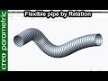
Designing Flexible Pipes in Creo Parametric: A Step-by-Step Guide
In this video, Satyendra guides viewers through the process of designing flexible pipes using Creo Parametric. The tutorial covers essential steps, including template selection, sketching techniques, and creating 3D models, making it suitable for both beginners and experienced users.
Most viewed summaries

A Comprehensive Guide to Using Stable Diffusion Forge UI
Explore the Stable Diffusion Forge UI, customizable settings, models, and more to enhance your image generation experience.

Kolonyalismo at Imperyalismo: Ang Kasaysayan ng Pagsakop sa Pilipinas
Tuklasin ang kasaysayan ng kolonyalismo at imperyalismo sa Pilipinas sa pamamagitan ni Ferdinand Magellan.

Mastering Inpainting with Stable Diffusion: Fix Mistakes and Enhance Your Images
Learn to fix mistakes and enhance images with Stable Diffusion's inpainting features effectively.

Pamamaraan at Patakarang Kolonyal ng mga Espanyol sa Pilipinas
Tuklasin ang mga pamamaraan at patakaran ng mga Espanyol sa Pilipinas, at ang epekto nito sa mga Pilipino.

How to Install and Configure Forge: A New Stable Diffusion Web UI
Learn to install and configure the new Forge web UI for Stable Diffusion, with tips on models and settings.
Found this summary useful?
Take it with you. One click puts it in your own LunaNotes library.
Save to LunaNotes