Introduction to Clocked D Latches
A clocked D latch is a fundamental one-bit memory device controlled by a clock signal. It stores a single bit (0 or 1) and changes its output only when enabled by the clock, allowing synchronization in multi-latch systems. To build foundational understanding, you might find Understanding Gated Dlatches: One-Bit Memory Devices Explained valuable.
Operation of a Basic D Latch
- The output Q follows the input D only while the enable input (E) is high.
- When E is low, Q retains its value regardless of changes in D.
- Multiple D latches can be connected with the same enable signal to hold multi-bit data.
Synchronizing with a Clock Signal
- The enable input E can be driven by a clock generating a square wave alternating regularly between high and low.
- While E (clock) is high, Q follows D; when low, Q holds its value.
- Challenges arise because enabling half the clock cycle (up to 50 microseconds) may be too long for some sensitive applications.
Edge-Triggered D Latches (Pulse Latches)
- To control changes more precisely, devices are designed to be enabled only on the rising edge of the clock, the brief moment when the signal goes from low to high (a few nanoseconds).
- Edge detection is implemented using logic gates like NOT and AND in a configuration that produces a very short pulse when the clock rises.
- This pulse enables the latch only momentarily, preventing unwanted changes outside this window.
Edge Detection Circuit Details
- The combination of a NOT gate and an AND gate creates a brief high output only when the input transitions from low to high.
- This positive edge detection output triggers the D latch to sample input D only at that moment.
Advantages of Edge-Triggered Latches
- Better synchronization across multiple latches and components.
- Avoids data instability caused by longer enable times.
Further Enhancements
- Pulse Width Adjustment: Adding extra NOT gates increases pulse duration if needed.
- Negative Edge Triggering: By inverting inputs or using a NOR gate, latches can be triggered on the falling edge of the clock.
- Asynchronous Inputs: Adding preset and clear inputs allows unconditional setting or resetting of the latch, independent of the clock, useful for initialization. For deeper insight into asynchronous controls, see Understanding Gated SR Latches: Operation and Applications Explained.
Symbols and Terminology
- The clock input on edge-triggered latches features a triangle symbol indicating dynamic, edge-sensitive behavior.
- A small circle notation indicates negative edge triggering.
Applications of Clocked D Latches
- Memory cells storing bits in registers and memory blocks.
- Counters and shift registers for data conversion and arithmetic operations.
- Synchronized timing control in complex digital systems.
Summary
Clocked D latches are key memory elements that respond to clock signals for controlled data storage. By adding edge detection circuitry, these latches become pulse latches (or edge-triggered flip-flops), sampling inputs only on clock transitions. Asynchronous preset and clear signals provide initialization capabilities, making these devices versatile in digital electronics. For a practical approach to programming such devices and designing digital systems, consider reading Mastering Verilog: A Comprehensive Guide to Digital Design and Programming.
in this video I'm going to talk about the clocked D latch that is a DCH controlled by a clock
signal we'll see how an edge detection device can be used to convert a clock signal into a series of very short
pulses thereby giving closer control over the behavior of a latch previously we looked at the Gat D
latch otherwise known as the data latch or simply the D latch a DCH is a one bit memory device it can
capture and store one bit of data that is a one or a zero let's quickly review the operation of a d latch on a timing
diagram before we see how it can be enhanced we previously saw that while e is high that is while the latch is
enabled the output at Q follows the input at D when e becomes low Q will retain its
current value no matter what changes are happening at D that's fine for some applications but
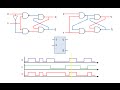
to build a buffer that can hold on to a multi-bit binary number we need several D latches working in
tandem when it comes to changing the data in such a circuit we need to be able to synchronize the setting of these
latches with each other and of course with other circuits inside the computer this can be done by connecting
the E inputs of several D latches to the same signal and this signal can be provided by a
clock in computer science a clock is a device that regulates all kinds of operations it does so by generating an
electrical signal that alternates between high and low at regular intervals there are several clocks
inside a typical computer running at different frequencies let's take a look at the
operation of a clock controlled DCH on a timing diagram
we're starting with d and q both at zero and D is at zero so the D latch isn't enabled e is connected to a clock so
this input is alternating between high and low you can see here the typical Square wave of a clock being applied at
input e we'll examine the effect of this particular sequence of changes in input
D whenever e is high Q is the same as D remember Q follows d q doesn't change while e is low so
this is the sequence of outputs that we can expect at Q this is still not a perfect solution
for synchronizing some components depending on the frequency of the clock the enabling input might be high for as
much as 50 micros seconds at a time that's a long time for the data latch to be open to changes in
D for some applications particularly those in which the outputs are fed back to the inputs we can avoid disorder by
drastically limiting the amount of time during each clock cycle that the latch can change
State simply increasing the frequency of the clock isn't necessarily a practical solution given that a computer contains
a mixture of fast and slow components so rather than having a DCH that's enabled for the entire duration
of half a clock cycle at a time we can modify the circuit so that it's only enabled while the clock input is
changing from low to high a change which takes in the order of only a few Nan seconds this brief period is known as
the rising Edge or the positive edge of the clock cycle we want to build a d latch that
will only respond to changes in D at the rising Edge subsequent changes in D being ignored until the next Rising Edge
Edge so how can we add an edge detection device to a d latch consider this combination of logic
gates for a moment a not gate with an and gate one input of the and gate is always
the inverse of the other this is how you might expect it to behave when we input a one into the
circuit the inputs of the and gate are one and zero so the output is zero when we input a zero into the circuit the
inputs of the andate are zero and one so the output is zero let's call the input C the laws of
Boolean algebra and the rules of combinational logic tell us that c and not C is
zero the fact is however that the not gate doesn't invert its input instantly when the input transitions from low to
high there's a very very brief period when the output the not gate is the same as its input this means that for the
same very brief period both inputs of the and gate are high and therefore so is its output when the not gate catches
up everything is once again as we'd expect similarly when the input transitions from high to low there's
another very brief period in which the knot gate must catch up but notice that this doesn't affect the output of the
endgate what we have here then is a device that can detect the very brief instant at which an input rises from low
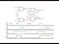
to high let's examine the operation of this Edge detecting circuit on a timing
diagram the top chart shows a clock signal being applied to the input the lower chart shows the corresponding
output the output of this circuit is low most of the time but you can see that when the input changes from low to high
there's a very brief moment in which the output of the knock gate lags behind its input so momentarily the output of this
circuit is also High we've isolated just the rising edge of the clock cycle what we have here
then is a positive Edge detection device here's our D latch again when we install our Edge detection device at e
we can rename the enabling input to c c for clock our D latch has been changed from a level triggered device into an
edge triggered device some people would Now call this a flip-flop and by many definitions they'd be correct a
flip-flop being a clock Edge triggered by stable which can be in one state or another purists however would argue that
this is actually a pulse latch but it does now behave some like a flip-flop albeit with some
limitations I'll talk about true flip-flops in a later video the clocked D latch has its own
symbol notice the addition of a triangle next to input C indicating the dynamic nature of the clock
input so let's analyze Its Behavior on a timing diagram D is sampled whenever there's a
rising Edge in the clock cycle for the rest of the time the device is latched Q can't change so this
is what we would expect from an EDG triggered D latch somewhat different from its level triggered
counterpart we can alter the behavior of our clocked D latch with some further modifications one of the problems with
using particular Edge detection device is the pulse thit producers may not be wide enough to open the latch and let
data in this depends on all kinds of factors including the operating characteristics of the electronic
components and the specific voltage levels being applied we can increase the delay of our
Edge detector and therefore the pulse width by adding some more knot Gates of course we need to make sure there's an
odd number of KN gates to invert the signal if needs be we could build a falling
Edge detector and therefore a Negative Edge triggered pulse Latch by immediately inverting the input signal
of our original device alternatively we could use a orgate in place of the and gate when
both inputs to the Norgate are momentarily low at the Negative Edge of the clock cycle will'll get a high
output a Negative Edge triggered device has a slightly different symbol notice the addition of a small circle at the
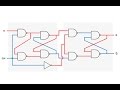
clock input which typically represents inversion another enhancement we can make is to add an extra pair of inputs
called preset and clear the only thing that's changed here is we're using three input nand Gates
now and as with any nand gate only when all of the inputs are high is the output low so when preset and clear are both
kept high they make no difference to the latching behavior when it's enabled at the rising
edge of the clock if D Falls to zero then so does q at the rising Edge if D becomes one
then so does q but during most of the clock cycle while this circuit is latched if clear
is made low then Q will fall to zero no matter what the current state of the flip-flop and no matter what the input
at D and in a similar fashion if preset is made low Q will become one
unconditionally preset and clear are known as asynchronous inputs they bypass the gating system of the latch so they
don't depend on the clock these active low inputs are particularly useful when you want to initialize a group of
latches either with zeros or ones we can now update the symbol we're using for our clocked D latch to include
preset and clear to summarize then a clocked D latch is a
onebit memory device which as its name suggests is enabled or disabled by the clock it has a range of uses for example
in memory circuits counters and shift registers a shift register can be used to convert parallel data into serial
data and vice versa or to perform binary multiplication more on these later a D latch can be EDG triggered
making it easy to synchronize its operation with other components this particular variation of
a clocked D latch is referred to as a pulse latch and sometimes although debatably as a
flip-flop if it's positive Edge triggered it means it's enabled when the clock signal is rising from low to high
if it's Negative Edge triggered it's enabled while the clock signal is falling from high to
low a clocked D latch can also have asynchronous preset and clear inputs which are used to initialize it
unconditionally
The pulse width can be increased by adding additional NOT gates in the edge detection circuit, which extends the duration of the enable pulse. This adjustment allows the latch to remain momentarily enabled longer if required by the application.
A triangle symbol on the clock input denotes an edge-sensitive (dynamic) input, meaning the latch responds to transitions rather than the level of the clock signal. A small circle symbol indicates negative edge triggering, where the latch activates on the falling edge (high to low transition) of the clock signal.
A basic clocked D latch changes its output whenever the clock (enable) signal is high, allowing the output to follow the input continuously during that period. In contrast, an edge-triggered D latch (or flip-flop) responds only at the precise moment of a clock signal transition (rising or falling edge), sampling the input briefly to avoid data instability during the clock cycle.
Edge detection circuits use logic gates such as NOT and AND gates to generate a very short pulse only during the clock's transition from low to high. This pulse enables the latch momentarily, ensuring the latch samples the input exactly at the clock edge, preventing unwanted changes during the rest of the clock cycle.
Asynchronous preset and clear inputs allow the latch to be set or reset immediately, independent of the clock signal. This functionality is vital for initializing the latch to a known state during system startup or to recover from errors, enhancing the reliability and control of digital circuits.
Clocked D latches are used for storing bits in registers and memory blocks, forming counters and shift registers, and providing synchronized timing control in complex digital systems. They ensure data is stored and transferred reliably by coordinating with clock signals.
Heads up!
This summary and transcript were automatically generated using AI with the Free YouTube Transcript Summary Tool by LunaNotes.
Generate a summary for freeRelated Summaries
Understanding Gated Dlatches: One-Bit Memory Devices Explained
This article explains the construction and operation of gated Dlatches, built from gated SR latches, and explores their behavior using timing diagrams. Learn how Dlatches function as one-bit memory devices, their advantages over SR latches, and their applications in data storage and transfer.
Master-Slave D-Type Flip-Flops: Ensuring Reliable Digital Circuit Timing
This summary explains the importance of clock synchronization in digital circuits and how propagation delays affect circuit stability. It details the design and function of master-slave D-type flip-flops, illustrating how they prevent glitches and ensure data integrity across clock cycles.
Understanding Gated SR Latches: Operation and Applications Explained
Explore how gated SR latches enhance control in digital circuits by enabling state changes only when permitted. This guide covers the design differences between NOR and NAND based gated SR latches, their timing behavior, and practical uses such as independent room cooling control in air conditioning systems.

Mastering Verilog: A Comprehensive Guide to Digital Design and Programming
Unlock the secrets of Verilog programming for digital systems. Learn from basics to advanced topics with ease!
Understanding Inductors in Circuit Theory: A Deep Dive
Explore the complexities of inductors in circuit theory with this comprehensive guide.
Most Viewed Summaries

A Comprehensive Guide to Using Stable Diffusion Forge UI
Explore the Stable Diffusion Forge UI, customizable settings, models, and more to enhance your image generation experience.

Kolonyalismo at Imperyalismo: Ang Kasaysayan ng Pagsakop sa Pilipinas
Tuklasin ang kasaysayan ng kolonyalismo at imperyalismo sa Pilipinas sa pamamagitan ni Ferdinand Magellan.

Mastering Inpainting with Stable Diffusion: Fix Mistakes and Enhance Your Images
Learn to fix mistakes and enhance images with Stable Diffusion's inpainting features effectively.

Pamamaraan at Patakarang Kolonyal ng mga Espanyol sa Pilipinas
Tuklasin ang mga pamamaraan at patakaran ng mga Espanyol sa Pilipinas, at ang epekto nito sa mga Pilipino.

How to Install and Configure Forge: A New Stable Diffusion Web UI
Learn to install and configure the new Forge web UI for Stable Diffusion, with tips on models and settings.

If you found this summary useful, consider buying us a coffee. It would help us a lot!