Overview of the Project
This project demonstrates an automatic power factor correction system utilizing Arduino. The main goal is to correct the power factor based on different load types, including resistive, inductive, and capacitive loads.
Load Types Used
- Resistive Load: 100 W
- Inductive Load: 40 W
- Capacitive Load: 2 microfarads at 440 volts AC
Power Factor Basics
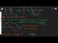
- The power factor decreases when inductive loads are connected, dropping from unity (1) to around 0.8 or 0.7 due to the lagging current waveform.
- With resistive loads, the phase difference between voltage and current is minimal, resulting in a power factor close to 1 (e.g., 0.99 or 0.995).
System Operation
- Monitoring: The system continuously monitors the voltage and current waveforms using current transformers (CT) and voltage transformers (PT).
- Phase Difference Calculation: The phase difference is calculated to determine the power factor. If the power factor is below 0.9, the system activates an electromagnetic relay to add capacitors, compensating for the lagging current.
- Compensation: Adding capacitors leads the current waveform, counteracting the lag from the inductive load, thus improving the power factor back towards unity.
- Display: The power factor values are displayed on a 16x2 LCD screen for real-time monitoring.
Demonstration Steps
- The system starts in a normal condition with a power factor of 0.95.
- When the inductive load is activated, the power factor may drop to 0.96, prompting the relay to connect the capacitor.
- Isolating the inductor leads to a leading power factor, demonstrating the system's ability to adjust and maintain efficiency.
Conclusion
This project effectively showcases how an Arduino-based system can automatically correct power factor issues, enhancing energy efficiency in electrical systems. For those interested in further exploring Arduino applications, check out our Comprehensive Guide to Arduino Programming: New Tutorials. Additionally, understanding the implications of power factor correction can be enhanced by reviewing Calculating Motor Efficiency: A Step-by-Step Guide, which discusses efficiency in electrical systems. If you're curious about sustainable energy solutions, consider reading Understanding the Cantic Road Concept: A Sustainable Energy Solution.
Welcome to the project demonstration of automatic power factor correction by using Arduino. So the main application
of this project is we are going to do the power factor correction based on the load. So as of now we are using the 100
Ws resistive load and here we using this 40 W of inductive load and the next capacitive load we are using 2
microfarad is 440 volt AC. So three loads R, L and C. So as we know that whenever the inductive load connected
then the power factor will comes down from unity to around 8 or 7 based on the power factor lagging of the current
waveform. So whenever the resistive load is occurred then the phase difference between the voltage waveform and current
waveform is near to the zero means the two waveforms will overlap with the phase difference of zero angle. Then cos
theta is nothing but the power factor value. So based on this phase difference the power factor value calculated. So
when we use the resistive load then it's going to be the near to zero then cos0 is near to unity power factor. So
whether it is a.99 or.995 based on this resistive load and when we add the inductive load in series
with the resistive load then the voltage will be divided in our project the voltage will be divided so that the bulb
industry will be decreases as we have added the inductive load. Due to that the current waveform will be lags. So
that we can get the phase difference between the voltage waveform and current waveform. That phase difference may be
10° or 20°. Based on that the power factor will be getting that 08 or 7 lakhs and uh due to that the system will
identify the power factor lagging and when it is less than.9 lags then the system will add this electromagnetic
relay to compensate this power factor by adding the capacitor. So nothing but when we add the capacitor the capacitor
will lead the current waveform. So that already the current waveform lagged by the L load this inductive load and there
will be lead by this capacitive load. So that the power factor value will be compensated based on this current
waveform compensation means it lags and it will lead the current waveform so that the phase difference will be comes
down to zero again so that the power factor also will be increased and which will be coming near to the one. So
whenever the power factor value is above 0.9 it's a normal condition and 0.9 lags is a normal condition and whenever the
power factor is less than.9 lagging then the system will on this relay to add this capacitor in parallel to the R and
C LO and whenever we isolate this inductor then only R + L will be R + C will be there so then here the power
factor will be leads so that will be identified again the microcontroller and the Arduino you know and it will be
isolate this relay capacitor to separate this RN plus C and here we are using this current transformer and voltage
voltage transformer. So from this CT and PT continuously the system will get the voltage waveform and current waveform.
And here is this zero crossing detector to get the current waveform directly. Uh it has a inbuilt zero crossing djector.
It will provide us the uh voltage waveform here. And the overall monitoring of this power factor values
will be displayed on the 16x2 LCD screen. And we have interfaced that at pin number B 22 to7 and pin number 9 to
this electromagnetic relay and A1 to this zero cross injector of voltage waveform and current waveform. This is
switch to isolate and connect the inductor load. So let us check with the demonstration. So when we on the power
supply so it is a normal condition. Okay. Just reset this. Wait till the power factor stabilized. So full
brightness nothing but the power factor value lags is 0.95 right whenever the lagging power
factor shows 0.96 continuously then we can on the inductor means R + L so that current may lags and the capacitor
connected in parallel to this R + L loads using this relay and whenever we are isolating this inductor again as you
can see the brightness and here you can see leading power factor so that the relay will switch it off. So in this
manner power factor lagging and less than nine compensation and when we isolate this again leading power factor
and isolate this relay right thank you.
The main objective of this project is to automatically correct the power factor in electrical systems based on different load types, including resistive, inductive, and capacitive loads. This helps enhance energy efficiency by ensuring that the power factor remains close to unity.
The system continuously monitors voltage and current waveforms using current transformers (CT) and voltage transformers (PT). It calculates the phase difference between voltage and current to determine the power factor. If the power factor falls below 0.9, the system activates a relay to add capacitors for correction.
The project uses three types of loads: a resistive load (100 W), an inductive load (40 W), and a capacitive load (2 microfarads at 440 volts AC). Inductive loads typically decrease the power factor due to lagging current, while resistive loads maintain a power factor close to 1.
When the inductive load is activated, the power factor may drop to around 0.96. This triggers the system to connect a capacitor via a relay, which helps to counteract the lagging current and improve the power factor back towards unity.
The power factor values are displayed on a 16x2 LCD screen, allowing for real-time monitoring of the system's performance and adjustments.
Using an Arduino for power factor correction provides a cost-effective and flexible solution for monitoring and adjusting power factor in real-time. It allows for automation, improving energy efficiency and reducing electricity costs.
For more resources on Arduino programming, you can check out the 'Comprehensive Guide to Arduino Programming: New Tutorials.' Additionally, for insights on power factor correction and energy efficiency, consider reviewing 'Calculating Motor Efficiency: A Step-by-Step Guide' and 'Understanding the Cantic Road Concept: A Sustainable Energy Solution.'
Heads up!
This summary and transcript were automatically generated using AI with the Free YouTube Transcript Summary Tool by LunaNotes.
Generate a summary for freeRelated Summaries
Understanding Resonant Converters: Inverter and Rectifier Modeling Explained
This video provides a detailed exploration of resonant converters, focusing on their construction, operation, and modeling. Key topics include the role of inverters, resonant networks, and rectifiers, with an emphasis on first harmonic approximation and the distinction between current-driven and voltage-driven rectifiers for efficient DC-DC conversion.

Designing a Solar Power Generation System for Homes Using MATLAB Simulink
This video tutorial guides viewers through the process of designing a solar power generation system for homes using MATLAB Simulink. It covers essential components such as solar panels, inverters, boost converters, and passive filters, explaining their roles in converting solar energy into usable AC power.

Understanding the Cantic Road Concept: A Sustainable Energy Solution
This seminar presentation explores the innovative Cantic Road concept, which harnesses kinetic energy from vehicles to generate electricity. It covers the technology behind the system, its benefits, challenges, and a case study demonstrating its practical application.

Understanding LCR Circuits: A Guide to AC Circuit Theory
Learn about LCR circuits, AC current, and the application of complex numbers in circuit analysis.

Innovative Automation Solutions at Rockwell Automation
Rockwell Automation is pioneering a new line of automation products that set benchmarks in quality and technology. The development of the retro and cababulator, an advanced instrument for synchronizing Cardinal Graham meters, showcases the company's commitment to customer success and operational excellence.
Most Viewed Summaries

A Comprehensive Guide to Using Stable Diffusion Forge UI
Explore the Stable Diffusion Forge UI, customizable settings, models, and more to enhance your image generation experience.

Kolonyalismo at Imperyalismo: Ang Kasaysayan ng Pagsakop sa Pilipinas
Tuklasin ang kasaysayan ng kolonyalismo at imperyalismo sa Pilipinas sa pamamagitan ni Ferdinand Magellan.

Mastering Inpainting with Stable Diffusion: Fix Mistakes and Enhance Your Images
Learn to fix mistakes and enhance images with Stable Diffusion's inpainting features effectively.

Pamamaraan at Patakarang Kolonyal ng mga Espanyol sa Pilipinas
Tuklasin ang mga pamamaraan at patakaran ng mga Espanyol sa Pilipinas, at ang epekto nito sa mga Pilipino.

How to Install and Configure Forge: A New Stable Diffusion Web UI
Learn to install and configure the new Forge web UI for Stable Diffusion, with tips on models and settings.

If you found this summary useful, consider buying us a coffee. It would help us a lot!