Introduction to Faraday's Law and Electromagnetic Induction
This lecture addresses the complex yet foundational concepts of electromagnetic induction discovered by Faraday and their implications in physics and technology.
Relationship Between Electricity and Magnetism
- Oersted's 1819 discovery: A steady electric current produces a steady magnetic field.
- Faraday's hypothesis and experiments revealed that a changing magnetic field induces an electric current, not a steady magnetic field. This relationship forms the basis explained in Understanding Electromagnetism: Key Concepts and Principles.
Key Phenomena and Laws
Electromagnetic Induction
- Moving a magnet towards or away from a conducting loop induces a current due to the changing magnetic field.
- The induced current opposes the change in magnetic flux, a concept formalized as Lenz's Law.
Lenz's Law
- States that the direction of an induced current will oppose the change in magnetic flux.
- Essential for determining current direction without knowing magnitude. See more detail in Understanding Faraday's Law and Lenz's Law: A Comprehensive Guide.
Magnetic Flux
- Defined as the integral of the magnetic field (B) over a surface area (dA): φ = ∫ B·dA.
- Only changes in magnetic flux induce an EMF according to Faraday's Law, as elaborated in the Comprehensive Guide to Electromagnetic Induction and Inductance Principles.
Faraday's Law of Induction
- The induced EMF in a closed loop equals the negative time derivative of the magnetic flux through the loop: EMF = -dφ/dt.
- This law generalizes earlier findings about induced current and flux changes.
Experimental Demonstrations
Induced Current and Changing Magnetic Fields
- Approaching and withdrawing a magnet from a coil induces currents that are detected and show the effect of magnetic flux change and Lenz's Law.
Effect of Loop Shape and Number of Turns
- The induced EMF depends on the number of loops of wire but not significantly on the loop's shape.
- Multiple turns multiply the induced EMF accordingly, foundational for transformer design.
Non-Conservative Electric Fields and Circuit Implications
- Unlike electrostatic fields, induced electric fields due to changing magnetic flux are non-conservative.
- Potential differences depend on the path taken in the circuit; hence, Kirchhoff's voltage law does not always hold in the presence of time-varying magnetic fields.
Illustrative Circuit Examples
- Comparison between a circuit powered by a battery and one powered by a time-varying magnetic field.
- Voltage measurements between points in the circuit differ based on measurement path when induced EMF is present, highlighting non-conservative nature.
Practical Understanding and Challenges
- Demonstrations show surprising experimental results that may challenge intuition, especially regarding voltage measurements.
- Emphasizes the importance of Lenz's Law and Faraday's Law in understanding and predicting circuit behavior where magnetic flux changes.
Conclusion
- The lecture highlights the profound and sometimes counterintuitive aspects of electromagnetic induction.
- Understanding these concepts is crucial for advanced studies in physics and electrical engineering, with applications spanning transformers to modern electronics.
For deeper exploration, students are encouraged to review homework solutions and engage in recitations which complement conceptual lectures with problem-solving techniques.
I'd like to thank you for your evaluations. They were very useful to me.
I already sent e-mail to about fifty students and I had some interesting exchanges with some of you. Many of you are very happy with their recitation instructors.
That's great. Many are moderately happy. Maybe that's OK.
But there are quite a few who are very unhappy with their recitation instructors. If you are very unhappy with your recitation instructor, you are complete idiots if you stay in that recitation.
We have thirteen recitation instructors, and can assure you that it will be very easy to find one that agrees with you and you can come and see me if that helps.
Some are better than others. That's the way it goes in life. Some students would like to see more cut-and-dried problem solving in my lectures.
I think that's really the domain of recitations. Lectures and recitations are complementary. In lectures, I prefer to go over the concepts
and I always give numerical examples to support the concepts, in a way that's problem solving, and I show demonstrations to further support the concept, because seeing, obviously, is believing.
I try to make you see through the dumb equations and admittedly my methods are sometimes somewhat different from what you're used to here at MIT.
I try to inspire you and at times I try to make you wonder and think. And I want to keep it that way. I believe that hardcore probling- problem-solving is really the domain of the recitations.
Many of you found the exam too easy and many of you found the exam too hard. Some complained it was too hard because it was too easy. [audience laughter]
Quite ironic, isn't it? They say, "We want more math, we want more standard problems." Look, who wants more math?
I'm teaching physics. I test you physics, I don't test you math abilities. If you digest the homework
and that's very important that you make the homework part of your culture, that you study the solutions. The solutions that we put on the web, today, four fifteen,
solutions through number four will go on the Web. Believe me, they are truly excellent solutions, not cut and dry. They give you a lot of background.
If you digest those solutions then the concepts will sink in. And now, at your fifty minute test, do you really want problems which are complicated maths?
Clearly, not. I could try that, during next exam, but then I may have to buy myself a bullet-proof vest to be safe.
Concepts is what matters. When I gave my exam review here, I highlighted the concept. Each little problem that I did here was extremely simple.
Conceptually, they were not so simple. But from a math point of view, trivial. Clearly, I can not cover all the subjects in a fifteen minute exam.
I have to make a choice, so your preferred topic may not be there. Some of you think that the pace of this course is too slow. Some of you think it's too fast.
The score, the average score, was three point eight. Four point zero would have been ideal. What do you want me to do?
I can't accommodate all of you. Those who think it's too slow and those who think it's too fast.
Three point eight is close enough to ideal for me, four point zero. And so I'll have to leave it the way it is. Besides that, keep in mind you are now at MIT.
You're no longer in high school. Now the good news. There were quite a few students who said the homework is too long.
Not a single person said it was too short. I can fix that. I will reduce all future assignments by about twenty-five percent, effective tomorrow.
I have already taken off assignment number five, two problems. You're down now to seven and I will do that, all assignments that are coming up. [applause]
My pleasure. Today, I'm going to cover with you something that conceptually is the most difficult of all of 802.
And you will need time to digest it. And if you think that what you're going to see is crazy, then you're not alone. The only good news is that conceptually, it's not going to become more difficult.
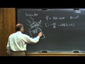
Remember that Oersted in 1819 discovered that a steady current produces a steady magnetic field, and that connected electricity with magnetism.
A little later, Faraday therefore suggested that maybe a steady magnetic field produces a steady current. And he did many experiments to show that.
Turned out to not to be so. And one way he tried that is as follows. He had here battery, with a switch and here he had a solenoid.
He closes the switch. A current will flow and that creates a magnetic field in the solenoid and that magnetic field, maybe it runs like so, depends on the direction of the current.
And so now, he put around this solenoid a loop. Let's call this loop number two and it was around the solenoid and let's call this loop number one, of which the solenoid is part.
Whenever there was a current in number one, he never managed to see a current in number two. If there is a current going in number one, there is a magnetic field
and that magnetic field is seen, of course, by the conductor number two by that loop. Never any current. And so he concluded that a steady magnetic field as produced by the solenoids, circuit one,
does not produce a steady current in number two. But then one day he noticed, that as he closed the switch he saw a current in number two, and when he opened the switch again he saw a current in number two
and therefore he now concluded that a changing magnetic field is causing a current. Not a steady magnetic field, but a changing magnetic field. And this was a profound discovery which changed our world and it contributed largely to the
technological revolution of the late nineteenth and early twenty century. A current, therefore an electric field, can be produced by a changing magnetic field, and that phenomenon is called electromagnetic induction,
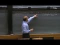
and that phenomenon runs our economy, as you will see in the next few lectures. I have here a conducting wire, a square. I could've chosen any other shape.
Try to make you see three dimensionally. And I approach this conducting wire with a bar magnet. The bar magnet has a magnetic field running like so.
As I approach that loop, that conducting wire, moving the bar magnet, that's essential. I can't hold it still. I have to move it.
If I come down from above and I move it down, you're going to see a current going through this loop. And that current will go into such a direction
that it opposes the change of the magnetic field. The magnetic field is in down direction and it is increasing as I move the bar magnet in.
Then this current loop will produce a magnetic field which is in this direction, and when you look from below the current will go clockwise, producing a magnetic field in this direction.
If you move the bar magnetic out, then the magnetic field is going down here, then the current will reverse. The current wants to oppose the change in the magnetic field
and that's called Lenz's Law. It is the most human law in physics, because there's inertia in all of us. We all fight change at some level.
Lenz's Law is extremely powerful in always determining in which direction these induced currents will run. It is not a quantitative law.
You can not calculate how strong the current will be, but it's very useful as you will see today to know the direction of that current that gets you out of all kinds of problems with minus signs.
I now want to do a demonstration which is very much like what you see here. I have here a loop. That is the square that you see there except that it's not-- not one loop,
but it is many of them. Hundreds, doesn't matter. And what we're going to show you is an amp meter that is connected,
so there is somewhere in this circuit an amp meter. I have a bar magnet and I'm going to approach this conducting loop with a bar magnet and you're going to see a current running in one direction
and when I pull it out it will be running in the opposite direction, and when I hold my hand still so that the magnetic field is not changing-- no current.
You're going to see the current meter there, and here is my bar magnet. I come close to this conducting loop. Notice we see a current.
I pull back, the current is in the other direction. Now I will go faster, so that the change of the magnetic field per unit time is stronger. [whistle]
More current. I go out fast. [whistle]
More current. So you see it's the change of the magnetic field that matters. If I come in very slowly, which I do now, very slowly, we almost see nothing.
Right now the entire magnetic field is inside this loop. The strongest I can have it. Nothing happens because there is no change in the magnetic field.
It's only when I do this that you see the current. So an induced current is clearly the result of a driving force. There must be, just like we had with batteries in the past, there must be an EMF.
There must be an electric field that is produced in this conducting loop. And so I create now an induced EMF-- we used that word EMF earlier for batteries, so now we have an induced EMF, which is the result of this changing magnetic field,
and that therefore is the induced current times the resistance of that entire closed conductor, whatever is in there. In this case, the total resistance of all these windings, of all the copper wire.
That's Ohm's Law. So the induced EMF is always the induced current times the resistance. Faraday did a lot of experiments, and one of the experiments that he did
was that he produced a magnetic field, so he ran a current through a loop of some kind, let's say he ran a current going around, creating therefore a magnetic field and he was switching the current in and out so that he could change the current
and so it produces a magnetic field and this magnetic field changes when you-- close and open the-- the switch. And then here, he had his second conducting wire, just like we had there,
and he measured in there the current. And what he found, experimentally, is that the EMF that is generated in here, which I will call EMF generated in my conducting loop number two,
is proportional to the magnetic field change produced by number one, so the field goes through number two and this field is changing, so he knows that if the change is faster, as you just saw, you get a higher EMF.
He also noticed that E two is proportional to this area, so to the area of number two. And that gave him the idea that the EMF really is the result of the change of the magnetic flux through this surface of number two.
And I want to refresh your memory on the idea of magnetic flux. We do know, or we remember what electric flux is. And magnetic flux, very similar.
If this is a surface and the local vector perpendicular to the surface is like so, of course it could be in a different direction and the local magnetic field is for instance like so, then a magnetic flux through this surface is defined.
We call it phi of B, is the integral over an open surface. This is an open surface of B dot dA. And the electric fields we defined in exactly the same way, electric flux,
except we had an E here. There was nothing there. So if this magnetic flux is changing, Faraday concluded,
that then you have an EMF in this conducting wire. So essential is the change of the magnetic flux.
If we take some kind of a conducting wire, like so, let's make it in the blackboard for now to make it easy. And I attach to this wire a surface because the moment that you talk about flux
you must always specify your surface. A flux can only go through a surface, so this is my surface now for simplicity. And there is a magnetic field coming out of the blackboard at me-- and it is growing.
It is increasing. I will now get an EMF, a current, flowing in this direction. Lenz's law.
If the magnetic field is increasing, then the current will be in such a direction that it opposes the change. It doesn't want that magnetic field to increase.
And so it goes around like this, the current, so that it produces a magnetic field that is in the blackboard. And so it is the flux change of that magnetic field through this flat surface
that determines the EMF. So the EMF is then the flux change, d phi dt, through that surface. To express Lenz's Law that it is always opposing the change of the magnetic flux,
we have a minus sign here. But minus signs will never bother you, believe me, because you'll always know in which direction the EMF is.
It's clear that the EMF is going to be in this direction. That's the direction in which it will make the current flow. But we have to put it there to be mathematically correct.
That's really Lenz's Law. You're looking at Lenz's Law here. So you can also write down for this: minus the surface integral of B dot dA
over that open-- whoo, I hope you didn't see this. Over this open surface. That's the [tape slows down]
Oops, look what I did. I forgot the DDT in front of the integral sign. Sorry for that.
[tape speeds up to normal speed] If you put yourself inside that conductor, and you marched around in the direction of the current,
you will see everywhere in the wire an electric field, of course. Otherwise, there would be no current flowing. And so if you go once around this whole circuit,
then that EMF must of course also be E dot dl over the closed loop. So you're marching inside the wire, you find everywhere an electric field and these little sections I dl.
E and dl are always in the same direction if you stay in the wire and so this should be the same and this is a closed loop. So this is all if you want what we call Faraday's Law.
We never see it in so much detail. I will abbreviate it a little bit on the board there. But I want you to appreciate that there is no battery in this circuit.
There is only a change in the magnetic flux through a surface that I have attached to the conducting wire and then I get an induced EMF and the induced EMF will produce a current
given by Ohm's Law. So I want to write down now on that blackboard there, Faraday's law in a somewhat abbreviated way
because we have all Maxwell's equations here and so we now have that the closed loop integral, closed loop of E dot dl-- that's that induced EMF.
You can take minus d phi dt or the time derivative of the integral B dot dA. That's the one I will take. Integral of B dot dA and this is over an open surface.
And that open surface has to be attached to this loop and that is Faraday. We have Gauss's Law, we have Ampere's Law. We have this one which tells you that magnetic monopoles don't exist.
This would only not be zero if you had a magnetic monopole and put it in a closed surface. Come and see me if you find one. And this now is Faraday's Law,
so you think that all four Maxwell's equations are now complete. Not quite. We're going to change this one shortly.
So we can't celebrate yet. We have to wait. It's the big party.
There's always a little bit of an issue about the direction of dA and I will explain to you how the convention goes but it really is not so crucial because Lenz's Law always helps you to find the direction of the EMF,
but if we are trying to be a purist, if this is my conducting loop and if I attach a flat surface to this, if I did that, and if I go around closed loop integral E dot dl,
Faraday doesn't tell me which way I have to go. I can go clockwise. I can go counterclockwise.
We will then do the same thing that we did before with Ampere's Law, apply the right-hand corkscrew rule and that is that if you march around clockwise, then dA will be in the blackboard, perpendicular to the blackboard,
perpendicular to this surface and if you go counterclockwise then dA will come towards you. The surface doesn't have to be flat.
It can be flat. There's nothing wrong with it. But there can also be a bag attached to it, as we also had earlier.
I have here a closed conducting wire and I could put a surface right here but I can also make it a [inaudible], like this, perfectly fine. Nothing wrong with that.
That's a open surface attached to this loop. That's fine. You have a choice and the convention with dA is then exactly the same,
that if you go clockwise then the dA would be in this direction using the right-hand corkscrew locally here. If you went counterclockwise, the DA would flip over.
So what is now the recipe that you have to follow? You have a circuit, electric circuit that determines then your loops, of course. You can take loops anywhere in space, but that's not too meaningful,
so you take them into your circuits, and so you define the loop first. Then you define the direction in which you want to march around that circuit. You attach an open surface to that closed loop
and you can determine on that entire surface the integral of B dot dA. Everywhere on that surface locally you know the dA, locally you know the B, you do the integration and you get your magnetic flux
and then if you know the time change of that magnetic flux, then you know the EMF. If you go around in this conducting circuit,
and you measure everywhere the electric fields, then the integral of E dot dl, if you go around the loop will give you the same answer and that connects the two.
The magnetic flux change is connected with the integral of E dot dl when you go around. And you have to take that minus sign into account. How come it doesn't matter whether you choose a flat surface or whether you choose a bag?
Well, think of magnetic field lines as a flow of water or spaghetti, if you like that, or a flow of air. It is clear that if there is some kind of a flow of air through this opening,
that it's got to come out somewhere, so it always comes out of this surface. And therefore, you're really free to choose that surface, so you always pick a surface that is the best one for you.
Now, all this looks very complicated. But in practice, it really isn't, because your loop is always a conducting wire in your circuit
and the minus sign is never an issue because you always know with Lenz's law in which direction the EMF is. In fact, when I solve these problems, I don't even look at the minus sign.
I ignore it completely. I def-- I calculate the magnetic flux change and then I always know in which direction the current is, so I don't even look at the minus sign.
Now I want to show you a demonstration which is very much like what Faraday tried to do. I have here a solenoid. We've seen this one before.
We can generate quite a strong magnetic field with that. And we're going to put around this solenoid one loop, like we had here, like Faraday did and then we're going to close the switch
and so we're going to build up this magnetic field and we're going to see the current in that loop. And so if we look-- if we make a cross-section straight through here,
then it will look as follows. Then you see here the solenoid, so the magnetic field is really confined to the solenoid. Magnetic field outside the solenoid as we discussed earlier is almost zero,
so there's only a magnetic field right here. Keep that in mind in what follows. And now we're going to put a wire around it, with an amp meter in there.
If the magnetic field comes out of the board, and is growing, is increasing, the current will flow in this direction. Lenz's Law.
If it is decreasing, the current will go in the opposite direction. Now keep in mind that the magnetic flux through this surface, that is, my surface which I attach to this closed loop,
that that magnetic flux remains the same whether I make the loop this big or whether I make the loop very crooked like so, because the magnetic flux is only confined to the inner portion of the solenoid
and that's not changing. And so when I change the shape of this outer loop, you will not see any change in the current.
I hope you-- that doesn't confuse you. I'm going to purposely change the size of the loop and so I'm going to do that now. You're going to see there a very sensitive amp meter--
and you're going to see here this loop, the big wire and I'm going to just put it over this solenoid. Let me first make sure that my amp meter which is extremely sensitive, I can zero it.
It's sign sensitive. If the current goes in one direction, you will see the needle go in one direction. If the current goes in the other direction, you will see the change.
And so now I put this loop around here, crazy shape this loop. So it's around this solenoid once, so the magnetic field is inside the solenoids and so think of a surface which is attached to this crazy loop
and now I'm going to turn the current on and only while the current is changing will there be a changing magnetic flux. Only during that portion will you see a current flow.
Three, two, one, zero. I will break the current, three, two, one, zero. Went the other direction.
If I change the size of the loop, I'm making it now different, much smaller. Makes no difference, for reasons that I explained to you, because the magnetic flux is not determined in this case by the size of my loop
but is determined by the solenoids, so if I do it again now, with a very different shape of the loop-- let me zero this again. Three, two, one, zero.
Three, two, one, zero. No change. Almost the same which you saw before.
Now comes something that may not be so intuitive to you. I'm now going to wrap this wire three times around. And so this outer loop, this outer conducting wire, is now like this.
One, two, three. Something like that. Now I have to attach in my head a surface to this closed loop.
My god, what does it look like? What a ridiculous surface. Well, that's your problem, not Faraday's problem.
How can you imagine that there is a surface attached to this loop? Well, take the whole thing and dip it in soap. Take it out and see what you see.
The soap will attach everywhere on the conducting loop. And if this loop were like this, going up like a spiral staircase, you're going to get a surface that goes up like this.
But the magnetic fields go through all three of them. Therefore, the changing magnetic flux will go three times through the surface now and so Faraday says, fine, than you're going to see three times the EMF
that you would see if there were only one loop. And if you go thousand times around, you get thousand times the EMF of one loop. Not so intuitive.
So I'm around now once. I go around twice. And I go around a third time.
I have three loops around it now. I can zero that, but that's not so important. Three, two, one, zero and you saw a much larger current.
It's about three times larger because the EMF is three times larger. I break the current. We see it three times larger.
And this is the idea behind transformers. You can get any EMF in that wire that you want to, by having many, many loops. You can get it up to thousands of volts and that's not so intuitive.
So Faraday's law is very non-intuitive. Kirchoff's Rule was very intuitive. Kirchoff said when you go around a circuit
the closed-loop integral of E dot dl is always zero. Not true is you have a changing magnetic flux. If you have a changing magnetic flux, the electric fields inside the conducting wires
now become non-conservative. Kirchoff's Rule only holds as long as the electric fields are conservative. If an electric field is conservative and you go from point one to point two,
the integral E dot dl is independent of the path. That's the potential difference between two points, that's uniquely defined. That's no longer the case.
If you go around once with this experiment, you get a certain EMF, you go three times around, you get a different value. Your path is now different and that's very non-intuitive,
because you're dealing with non-conservative fields for which we have very little feeling. Now, I'm going to blow your mind. I'm going to make you see something that you won't believe--
and so try to follow step-by-step-- leading up to this unbelievable and very non-intuitive result. I have here a battery and the battery has an EMF of one volt.
Here is a resistor, R one, which is hundred ohms. And here is a resistor, R two, which is nine hundred ohms. And I'm asking you what is the current that is flowing around.
And you will laugh at me. You will say that's almost an insult. I wish you had given that problem at the first exam,
because E equals the current that is going to run, divided by R one plus R two. [tape slows down] Oh, my goodness, what did I do.
[Lewin laughs] I forgot Ohm's Law. E equals IR, remember, not I over R.
So R one plus R two should go upstairs. And everything that follows is correct, so you don't have to worry about that. This was just a big slip of the pen.
[tape back to normal speed] And so the current I is ten to the minus three amperes. One milliampere.
Big deal. Easy. Current is going to flow like this.
Fine. Let's call this point D and call this point A. And I asked you what is the potential difference between D and A.
You will be equally insulted. VD minus VA, you apply Ohm's Law, you say that's this current times R two. Absolutely.
I times R two. But that is plus oh point nine volts. Now I say to you, well, suppose you had gone this way,
then you would've said, "Well, I find the same thing, of course." Kirchoff's Rule. So indeed, if you go VD minus VA, and you go this way,
then notice this battery, this point is one volt above this point. But you have in the resistor here, you have a voltage drop according to Ohm's Law, and the current times hundred ohms gives you a one-tenth voltage drop here,
so VD minus VA is the one volt from the battery minus I times R one, and that is plus oh point nine volts. What a waste of time that we did it twice and we found the same result.
So I connect here a voltmeter. The voltmeter is connected to point D and to point A. And I asked you what are you going to see.
The answer is plus oh point nine volts and you will provided that the plus side of the voltmeter is connected here and the minus side of the voltmeter there.
Voltmeters are polarity sensitive. This is fine. Kirchhov's rule works.
The closed loop integral from E dot dl going from D back to D is zero. So far, so good. Now, hold on to your chairs.
I'm going to take the battery out. Who needs the battery. I'm going to replace the battery by a solenoid--
which you see right here, and this solenoid when I switch it on is creating an increasing magnetic field. Only here, and let's assume that that increasing magnetic field is coming out of the board,
and that it is increasing. Lenz's Law will immediately tell you in what direction the current is. If this magnetic field is increasing towards you, the current will be in this direction.
The magnetic flux change, d phi dt, at a particular moment in time, happens to be one volt. An amazing coincidence, isn't it. E induced at a moment in time is one volt.
Now, I ask you, what is the current? Well, you'll be surprised that I even have the courage to ask you that, because Ohm's Law holds.
The induced EMF is one volt and R one plus R two is still a thousand ohms, so ten to the minus three amperes. I really make a nuisance of myself when I say, "What is VD minus VA?"
and you get annoyed at me and you say, "Look, the current I through R two, Ohm's Law, V equals IR, plus oh point nine volts." And then I say, but now suppose we go the other-- the other side,
and we want to know now what VD minus VA is, and now it's not so simple, because there's no battery. And so now when I go from D to A, I don't have this one,
and therefore I now find minus oh point one volts. I find a totally different answer. I attach a voltmeter here.
That voltmeter will show me plus oh point nine volts. Now I attach a voltmeter here, the same one. I flip it over.
It's connected between point D and point A. It will read minus oh point one volts. This voltmeter, which is connected between D and A, reads plus oh point nine.
This voltmeter which is connected to D and A reads minus oh point one. The two values are different and I placed on the web a lecture supplement which goes through the derivation step-by-step,
which will convince you that indeed this is what is happening. Why we can't digest this so easily is we don't know how to handle non-conservative fields. If you have a non-conservative field, then if you go from A to D of E dot dl
or from D to A for that matter, doesn't matter, the answer depends on the path. It's no longer independent of the path. And so if here is D and here is A, and you go this way,
you find oh point nine volts, plus if you go this way-- you find minus oh point one volts. Faraday has no problems with that.
Kirchoff has a problem with that, but who cares about Kirchoff? Faraday is the law that matters, because Faraday's Law always holds, because if d phi dt is zero, then you get Kirchoff's.
Kirchoff's rule is simply a special case of Faraday's Law, and Faraday's Law always holds, so Kirchoff is for the birds and Faraday is not.
Suppose you go from D to A and back to D. Well, we know that VD minus VA, if we go through this--
if we go this way, through R two, we know that VD minus VA is plus oh point nine volts. Now we are at A and we go through the left side back to D. So we now have VA minus VD.
That of course is now plus oh point one volts, because remember, if VD minus VA is minus oh point one, then VA minus VD is plus. And so we add them up and we find that VD minus VD is plus one volts.
Kirchoff said, has to be zero, because I'm back at the same potential where I was before. Faraday says, uh-uh, I'm sorry, you can't do that. That one volt is exactly that EMF of one volt.
That is the closed loop integral of E dot dl around that loop. It's no longer zero. And therefore, whenever you define potential difference,
if you do that in the way of the integral of E dot dl, keep in mind that with non-conservative fields, it depends on the path and that is very non-intuitive.
And I'm going to demonstrate this now to you. I have a circuit which is exactly what you have here. I have nine hundred ohms in a conducting copper wire here
and I have a hundred ohms here and here is the solenoid. We can switch the current on in the solenoid and get a blast of magnetic field coming up and the system is going to react by driving a current in the direction that you see there.
And I'd like to be even a little bit more quantitative, so that you get a little bit more for your money. The magnetic field takes a little bit of time to reach the maximum value.
In this course, we will be able to calculate the time that it takes for the magnetic field to build up. We didn't get to that yet, so forget that part.
It's not so important. I just want you to appreciate the fact that the magnetic field as a function of time will come up like this and will then reach a maximum.
It's no longer changing. It's constant, it's a maximum value. It's very high, seven, eight hundred Gauss or so for this unit.
We are not interested in a magnetic field. We are interested in the change of the magnetic field, so the change of the magnetic field, dB dt, is going to be something like this,
that's the derivative of this curve. And that is proportional with the induced EMF and that's in por-- pro-- proportional with the current, through Ohm's law.
So if we now plot the voltage as a function of-- let me do that here, the voltage as a function of time, then that voltmeter on the right side,
I call that V two, will do this. This is V two, which is I times R two at the maximum value. If those values were correct it would be oh point nine volts
and V one would go like this. V one equals minus I times R one. That gives me the minus oh point one volts.
So the question now is what is the largest value of dB dt that we can expect. We also have to know the surface area of the solenoids so we can convert it to a flux change. Well, the change in magnetic field is roughly at the fastest here
is about hundred Gauss in one millisecond. Very roughly. So that would mean a field change, dB dt.
That's the maximum value possible only in the beginning of about ten Tesla per second. And the surface area, which is that inner circle there through which the flux is changing, the fact that my surface has to be attached to that loop doesn't change the magnetic flux.
The magnetic flux is only determined, of course, by that inner portion and so if the inner portion has an area of say ten square centimeters, which is ten to the minus two square meters,
then d phi dt will be approximately ten times ten to the minus two, so that's about oh point one and that's volts. That's EMF.
I don't care about the direction, because I know Lenz's Law. So you're going to see an experiment which is almost identical to what I have there, except all values are down by a factor of ten.
But that's all. And you're going to see that demonstration there. And a few years ago, when I first did this experiment in 26-100,
there were several of my colleagues, professors of both the physics department and EE department in my audience. And some did not believe what they saw.
In fact, it was so bad that after my lecture they came to me and some accused me for having cheated on the demonstration. This tells you something about them.
[people in the audience chuckle] Imagine, professors in physics and professors in electrical engineering department who did not believe what they were seeing.
That tells you how non-intuitive this is. The simple fact that we had one voltmeter connected to point D and A and another voltmeter connected to the same point,
they were unwilling to accept that the two voltmeters read a totally different value. They were not used to non-conservative fields.
Their brains couldn't handle it. But that's the way it is, and I'm going to show this to you now. You're going to see it there and when you see this demonstration,
it will be probably the only time in your life that you will ever see this and I want you to remember this. You're going to see something that is very strange
and I want you to tell your grandchildren about it, that you have actually seen it with your own eyes. You're going to see there on the left side, you're going to see V one
and on the right side you're going to see V two. The vertical scale is such that very roughly from here to here is about oh point one volts. And a horizontal unit is about five milliseconds
and the whole voltage pulse lasts about ten milliseconds, because from here to here is about ten milliseconds. And the value that you expect for V two will be nine times higher than V one
and the polarities will be reversed. If you're ready for this big moment in your life-- three, two, one, zero.
Look on the left. There's V one. Notice, it's negative.
Look on the right. There's V two. It's about nine times larger than V one.
Don't pay any attention to this wiggle. It has to do with the voltage that we apply, which is not exactly flat. And notice that the whole pulse goes from here to here, lasts about ten milliseconds.
The moment that the magnetic field reaches a maximum and remains constant, there is no longer any induced current. Think about this.
Give this some thought. This is not easy. And have a good weekend.
Faraday's Law states that the electromotive force (EMF) induced in a closed loop equals the negative rate of change of the magnetic flux through the loop (EMF = -dφ/dt). This means that whenever the magnetic field passing through a conducting loop changes over time, an electric current is induced. This principle explains how moving a magnet toward or away from a coil generates current in the wire.
Lenz's Law states that the induced current flows in a direction that opposes the change in magnetic flux that produced it. For example, if a magnetic field through a loop increases, the induced current creates its own magnetic field opposing this increase. This law helps predict the current direction without knowing its magnitude, ensuring consistency with conservation of energy.
The induced EMF primarily depends on the rate of change of magnetic flux, which is related to the magnetic field and the area of the loop, not its shape. However, the number of turns in the wire loop multiplies the induced EMF proportionally, because each loop acts as an independent conductor experiencing the same flux change. This principle is fundamental in designing transformers where multiple coils increase voltage.
Magnetic flux (φ) is defined as the integral of the magnetic field (B) over a surface area (A), essentially measuring how much magnetic field passes through the loop area. According to Faraday's Law, a steady magnetic flux does not induce current; only changes in magnetic flux—either by varying magnetic field strength, loop area, or orientation—produce an electromotive force and thus induce current.
Induced electric fields from changing magnetic flux are non-conservative, meaning the electric potential difference depends on the path taken in the circuit. This causes Kirchhoff's voltage law to sometimes fail in such conditions because voltage around a loop may not sum to zero. As a result, voltage measurements between two points can vary depending on the measurement path, which is important to consider in circuits exposed to time-varying magnetic fields.
Experiments commonly involve moving a magnet toward and away from a coil of wire while measuring the induced current or voltage. Approaching the magnet increases magnetic flux through the coil and induces a current in one direction, while withdrawing it decreases flux and reverses the induced current direction. These setups visually and quantitatively validate Faraday's and Lenz's laws by showing how changing magnetic conditions create electrical effects.
These laws underpin the operation of many electrical devices such as transformers, electric generators, and inductors. Understanding how changing magnetic fields induce currents enables engineers to design efficient power conversion and distribution systems. Moreover, grasping their sometimes counterintuitive implications helps troubleshoot complex circuits involving time-varying magnetic fields and guides advanced studies in electromagnetism.
Keep this summary
Save it to LunaNotes and it becomes a real note in your library — editable, searchable, and ready to turn into flashcards or a diagram. Free to start.
Save to LunaNotesOr summarise for another video.
This summary and transcript were automatically generated using AI with the Free YouTube Transcript Summary Tool by LunaNotes.
Related summaries
Understanding Faraday's Law and Lenz's Law: A Comprehensive Guide
Explore Faraday's law, Lenz's law, inductors, and electricity generation in our detailed guide for physics enthusiasts.

Comprehensive Guide to Electromagnetic Induction and Inductance Principles
Explore the fundamental concepts of electromagnetic induction, Faraday's and Lenz's laws, motional EMF, self and mutual inductance, and practical applications including eddy currents and AC generators. Understand key experiments and mathematical formulations that explain how changing magnetic fields induce electric currents.
Understanding Ampere's Law and Its Application in Electromagnetism
Explore the fundamentals of Ampere's law, the behavior of magnetic fields in loops, and their implications in real-world phenomena.
Understanding Electromagnetism: Key Concepts and Principles
Explore the fundamentals of electromagnetism, including wave behavior, Maxwell's equations, and the relationship between electric and magnetic fields.
Understanding Magnetism: Forces, Currents, and Magnetic Fields
Discover the principles of magnetism, how currents create magnetic fields, and the forces involved, explained in simple terms.
Most viewed summaries

A Comprehensive Guide to Using Stable Diffusion Forge UI
Explore the Stable Diffusion Forge UI, customizable settings, models, and more to enhance your image generation experience.

Kolonyalismo at Imperyalismo: Ang Kasaysayan ng Pagsakop sa Pilipinas
Tuklasin ang kasaysayan ng kolonyalismo at imperyalismo sa Pilipinas sa pamamagitan ni Ferdinand Magellan.

Mastering Inpainting with Stable Diffusion: Fix Mistakes and Enhance Your Images
Learn to fix mistakes and enhance images with Stable Diffusion's inpainting features effectively.

Pamamaraan at Patakarang Kolonyal ng mga Espanyol sa Pilipinas
Tuklasin ang mga pamamaraan at patakaran ng mga Espanyol sa Pilipinas, at ang epekto nito sa mga Pilipino.

How to Install and Configure Forge: A New Stable Diffusion Web UI
Learn to install and configure the new Forge web UI for Stable Diffusion, with tips on models and settings.
Found this summary useful?
Take it with you. One click puts it in your own LunaNotes library.
Save to LunaNotes