Comprehensive Guide to Electromagnetic Induction and Inductance Principles
Introduction to Electromagnetic Induction
Electricity and magnetism are interrelated phenomena where changing magnetic fields induce electric currents. This principle is demonstrated through various experiments involving coils, magnets, and galvanometers.
Key Experiments Demonstrating Electromagnetic Induction
- Faraday's Experiments: Show that relative motion between a magnet and coil or between two coils induces an electromotive force (EMF). For a deeper understanding of Faraday's contributions, check out Understanding Faraday's Law and Lenz's Law: A Comprehensive Guide.
- Henry's Experiments: Confirm that changing magnetic flux through a coil induces current, observable via galvanometer needle deflections.
Fundamental Terms in Electromagnetic Induction
- Magnetic Flux (ΦB): Product of magnetic field strength (B), area (A), and the cosine of the angle (θ) between them, ΦB = B·A·cosθ.
- Magnetic Field (B): Number of magnetic lines of force per unit area.
- Area Vector (A): Vector perpendicular to the surface area considered.
Faraday's Law of Electromagnetic Induction
- The induced EMF in a coil is equal to the negative rate of change of magnetic flux through it: E = -dΦB/dt. For a coil with N turns, total induced EMF: E = -N·dΦB/dt.
Lenz's Law
- The direction of induced EMF opposes the change in magnetic flux that produces it. This law ensures conservation of energy and prevents perpetual motion. To explore this concept further, see Understanding Faraday's Law and Lenz's Law: A Comprehensive Guide.
Motional EMF
- When a conductor moves in a magnetic field, an EMF is induced: E = B·L·V, where L is conductor length and V is velocity. Explained by Lorentz force acting on charge carriers in the conductor.
Energy Conversion and Conservation
- Mechanical work done to move a conductor in a magnetic field converts into electrical energy and then heat. Power input equals power dissipated, confirming energy conservation.
Eddy Currents
- Circulating currents induced in conductors exposed to changing magnetic fields. Cause energy loss as heat; minimized by laminating cores in transformers and motors. Applications include electromagnetic braking and induction heating. For more on this topic, refer to Understanding Inductors in Circuit Theory: A Deep Dive.
Self Inductance
- A coil induces an EMF in itself when current changes, opposing the change. Self-inductance (L) relates flux linkage to current: NΦB = L·I. Induced EMF: E = -L·dI/dt. Energy stored in magnetic field: W = 1⁄2 L I2.
Mutual Inductance
- Change in current in one coil induces EMF in a nearby coil. Mutual inductance (M) depends on coil geometry and magnetic permeability. EMF induced in coil 1 due to current change in coil 2: E1 = -M·dI2/dt.
AC Generator Principles
- A rotating coil in a magnetic field produces alternating EMF: E = N·B·A·ω·sin(ωt). Slip rings and brushes transfer current to external circuits. For a comprehensive overview of AC generators, see Understanding Electromagnetism: The Basics of Forces, Mass, and Charge.
Summary
This guide covers the experimental foundations and mathematical descriptions of electromagnetic induction, including Faraday's and Lenz's laws, motional EMF, self and mutual inductance, and practical applications such as eddy currents and AC generators. Understanding these principles is essential for grasping how electrical energy is generated and manipulated in various devices.
Oh electricity and magnetism are interrelated and are also
interconvertible let us look at a few examples in this setup an electric current
passing through a conductor produces a magnetic field which can be observed through the
deflection of a magnetic compass needle placed near the conductor this proves that moving electric charges
produce magnetic fields electric motors work on this principle however in this Center we see that an
electric current is induced in a closed coil when subjected to a changing magnetic field the phenomenon in which
an electric current is generated by varying magnetic fields is called electromagnetic induction
electric generators work on this principle we will now discuss and learn about
three experiments by faculty and Henry relating to electromagnetism in the first experimental setup a coil
is connected to a galvanometer when a bar magnet with it's not fall facing the koi is moved to words or away
from the koi the galvanometer needle dislikes to the right and left side of zero reading respectively showing the
presence of a current in the coil now let us see what happens if the South Pole of the magnet faces the coin
the galvanometer needle dislikes to the left side of zero reading as the magnet approaches the coil and the Flex to the
right when the magnet moves away from the coil join the presence of a current in the
Kali the galvanometer needle deflects only as long as the bar magnet is in motion
once the bar magnet comes to rest the galvanometer needle settles down at zero reading indicating that there is no
current in the coil from all these observations we can conclude that whenever there is relative
motion between a bar magnet and a coil an electric current is induced in the coil
in the second experimental setup there are two coils coil one connected to a galvanometer coil to connect it to a
pantry due to the steady current in coil to a steady magnetic field is set up around
the coil - and this magnetic field is also linked to the coil one when coin to escape stationary and coin
one is moved towards coin too a current is induced in coil 1 and the galvanometer needle dislikes to the left
of 0 when going to escape stationary and kiwanis moved away from coil to
a current is induced in coil 1 and the galvanometer needle deflects to the right of 0
if we keep calling one stationary and move going to towards coil one a current is induced in coil 1 and a
deflection is observed in the galvanometer needle to the left of 0 now if we keep going one stationary
and move going to away from coit one a current is induced in coil 1 and a deflection is observed in the
galvanometer needle to the right of 0 from all these observations we can conclude that whenever there is relative
motion between a current carrying coil and a closed coil in which a galvanometer is connected a current is
induced in the closed coil in the third experiment the tab key is provided in the coil - second
here we can observe the deflection of the galvanometer needle even when the two coins are stationary
this deflection is observed only and those instants when the tab key is either switched on or off
this happens because of the change in magnetic field during switching on and off
when a ferromagnetic material like an iron truant is pleased coaxial e along the two coins
the effect of the magnetic field linked to the coin - increases due to the nature of the ferromagnetic material as
it allows more number of magnetic lines of force to link within the area of the cony
hence the deflection of the galvanometer needle increases indicating an increase in the induced current
before attempting to understand Faraday's law of electromagnetic induction we should lay capitulate the
terms used in electromagnetic induction these terms are representation of the surface area by a
vector e uniform magnetic field B and magnetic flux phi b
the area of a plane surface is represented by a vector a drawn along the outward normal to the plane surface
in the case of a curved surface this area is split into very small areas and each is approximated to a planar
area in a uniform magnetic field be the number of magnetic field lines cutting
across an area placed perpendicular to the fleet lines is same for each unit area of the surface
if a plaintiff area a is placed in a uniform magnetic field B with its area vector e making an angle theta with the
magnetic field then the magnetic flux 5b through the area can be written as Phi B is equal to
B dot a which is equal to B a cos theta the equation 1 magnetic flux Phi B can be varied by
changing any one or more of the terms B e and theta the SI unit of magnetic flux is Weber or
Tesla meters squared magnetic flux phi b is a scalar quantity when the magnetic field has different
magnitudes and directions at the various parts of a curved surface the magnetic flux through the curved surface is
computed by extending equation one phi b is equal to b 1 dot d a 1 plus B 2 dot d a 2 plus and so on which is equal
to Sigma all bi dot Dai let this be equation 2 so far we have recalculated the terms
used in electromagnetic induction learn about Faraday's experiments where we use these terms
party conducted three experiments from which he concluded that an EMF is induced in a coil when the magnetic flux
cutting across the coil changes with time in the first experiment
Baddeley observed that the relative motion between a magnet and a coil changes the magnetic flux across the
coin this change in magnetic flux with time induces an EMF in the coil
similarly in the second experiment he observed that the relative motion between the two coins one carrying a
current changes the magnetic flux across the coins this change in the magnetic flux with
time induces an EMF in the other coil in his third experiment with two coins he found that if the tab key is pressed
the current in coil two and the resulting magnetic field Rises from zero to maximum value in a short time
this results in a change in the magnetic flux with time across coil one inducing an EMF in it if the key is kept
pressed there is a steady magnetic field across coil one thereby there is no EMF induced in it and the current drops to
zero when the tab key is released the current and pointer decreases from a maximum
value to zero in a short time resulting in the magnetic flux across coil one to drop suddenly thereby inducing an EMF in
it from the observations of these three experiments Faraday concluded that the
time rate of change of magnetic flux through a closed coil induces an EMF through it and stated the Faraday's law
of electromagnetic induction the magnitude of the induced EMF in a circuit is equal to the time rate of
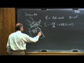
change of magnetic flux through the coil we can put this law in the form of a mathematical equation e is equal to
minus D Phi B divided by DT let this be equation three in this equation e is the induced EMF
the negative sign indicates the direction of EMF and hence the current in the closed-loop
when n number of turns are closely wound to form the coin the change of flux with time for each coin is the same and we
can write for the total induced EMF as e is equal to minus n into D Phi B divided by DT
let this be equation for in this equation e is the total induced e-m-f
the negative sign indicates the direction of EMF and hence the current in the closed loop therefore the total
induced EMF can be increased by increasing the number of turns n of the coil
before attempting to learn about lenses nor let us first recapitulate about the right hand grip rule applied to a
current carrying coil consider a right hand fist with the thumb extending out if the fingers are wrapped in a circle
pointing in the direction of the current through the coil then the thumb points towards the end of the coil indicating
the North Pole Lenz's law helps us in identifying the polarity of the induced EMF in a coin
Lenz's law states that the polarity of induced EMF in a closed loop is such that it tends to produce a
current which opposes the change in the magnetic flux that produces it we can put this statement in simple
terms if a current is induced by an increasing flux it will weaken the original flux
if a current is induced by a decreasing flux it was strengthened the original flux
the magnitude of the induced EMF is given by Saturday's law which is e is equal to minus D Phi B divided by DT
e is the induced EMF in the coin and Phi B is the magnetic flux the negative sign in this equation
represents the effect as stated in lenses law let us look at Saturday's experiments
and apply Lenz's law to them to identify the polarity of the induced EMF and the direction of induced current in the coin
in this experiment the coil which is connected to a galvanometer is at rest
a bar magnet with it's not full facing the coil is moved towards the coin this causes the magnetic flux through
the coil to increase a current is induced in the koi which opposes this increase in flux
the induced current is in the counterclockwise direction looking from the bar magnet site
this current produces a knock polarity towards the North Pole of the magnet and opposes the motion of the magnet thereby
opposing the increase in magnetic flux through the cony a force is required to move the magnet against this repelling
force the same magnet when moved away from the stationary coil causes the magnetic flux
through the coil to decrease a current is induced in the coil which opposes this decrease in flux
the induced current is in a clockwise direction looking from the bar magnet site
this current produces a south polarity towards the north pole of the receding magnet
this south pole attracts the north pole of the bar magnet thereby resisting the motion of the magnet
when the South Pole of the magnet is towards the coin and it is moved towards the coin a sound polarity is induced
near the South Pole of the magnet when the same magnet is moved away from the coil a north polarity is induced
near the South Pole in all these experiments we can also use an open circuit in the place of a closed
loop in this case to an EMS is induced but there is no induced current in the
coin the direction of this induced e-m-f can be found using lenses law
here is an easy way to understand the direction of induced currents and EMF we have so far taken lenses la for
granted suppose that the induced current is in the direction opposite to the one given
in the figure in that case the South Pole due to the induced current will be near the
approaching North Pole of the magnet causing the bar magnet to be attracted towards the coil
a gentle push on the magnet will start the process of motion and its velocity and kinetic energy will continuously
increase without expending any energy if this is true we can construct a perpetual motion machine with a suitable
arrangement this violates the law of conservation of energy and hence cannot happen
so we can conclude that lenses law is correct in all the experiments discussed a force
is required to move the magnet bar either towards or away from the coil the product of the force and the
distance moved gives the work done on the magnet work is done by spending some mechanical
energy by the person conducting the experiment the mechanical energy is converted to electrical energy in the
coin the electrical energy is converted into heat energy by heating up the coil which
is dissipated into the atmosphere from these observations we can say that the energy is only converted from one
form to another or the energy is concerned we have studied about induced EMF in a
circuit due to the rate of change of magnetic flux to the circuit this happens due to the relative motion
between the coil c1 and the bar magnet we know that the induced EMF E is equal to minus D Phi by DT where D Phi by DT
is the time rate of change of the magnetic flux and the minus sign is in accordance with the Lenz's law
let this be equation 1 now let us study about induced EMF produced due to the motion of a
conductor in a magnetic field consider PQRS to be a rectangular metallic loop having a galvanometer G
connected between R and s the part PQ can slide forwards or backwards in between the parts PS and
our cue of the loop let us now place PQRS in a uniform magnetic field such that its plane is
perpendicular to the magnetic field for a time independent magnetic field the magnetic induction B remains
constant both in magnitude as well as direction let the length of PQ be L and that of
our Q DX let the conductor PQ move towards the ends s start with a constant velocity V
we observed that the conductor PQ the direction of the magnetic induction B and the velocity V of the conductor
are mutually perpendicular to each other we see that the conductor initially is at a distance X from the RS end
as the conductor moves towards the RS end it is displaced from its original position and its velocity V can be
written as DX by DT since the plane of the loop is normal that is perpendicular to the magnetic
field maximum magnetic flux passes through the loop
this magnetic flux Phi be passing through the loop is equal to the product of the magnetic induction B and the area
a of the enclosed loop product of L and X represents the area swept B
hence we can now rewrite the magnetic flux 5b as equal to BL x since a equal to LX
as the conductor moves towards the RS end we see that X is varying and hence the area enclosed by the loop also
changes with the time therefore we see that magnetic flux phi b also changes with time as the magnetic
flux depends on the area enclosed hence according to principle of electromagnetic induction an induced EMF
is developed across PQ this induced EMF E is equal to minus D Phi B by DT as given by equation 1
substituting for phi b we get e is equal to minus d by dt of b LX as B and L are constant and only X is
the variable we can write e is equal to minus BL into DX by DT as DX by DT represents the velocity V of
the conductor P Q we can write electromotive force e is equal to minus B and V let this be equation two
[Music] the induced EMF E is also called the motional EMF in this case
the concept of motional EMF can also be explained by using the Lawrences force acting on the free charge carriers of
conductor PQ we know that when a charge Q enters perpendicular to a uniform magnetic
field of induction B then the Lawrences force on the charge FB is equal to QV b as the conductor moves with a speed V
free electrons in the conductor also moves with speed V in the magnetic field B in addition to the random velocity
they have within the metallic conductor PQ the average magnetic force due to the
random velocity is zero but the average magnetic force on each free electron due to velocity V is FB
equal to QV B where Q is the charge on the electron equal to minus 1 point 6 into 10 power minus 19 coulomb
from Fleming's left hand rule we can say that in this situation the magnetic force on a positive charge moving with
velocity V in this magnetic field we'll be along PQ in accordance with the same room we can
see that the force on the electrons FB will be directed along QP and we see that the three electrons in
the conductor move towards B as a result of this movement the negative charge builds up that P and
a positive charge appears at Q an electric field is developed within PQ such that the electric field exerts a
force F e equal to QE on each electron in electrostatic equilibrium the force F II will be equal to FB and
this build of charge stops since f n becomes equal to FB we have QE equal to QV be simplifying we get e
equal to VB due to the charge buildup a potential difference is developed across PQ which
is the induced EMF II we know that the potential difference e is equal to e into L substituting the value for the
electric field strength e equal to VB we get induced EMF e equal to b lv since Lenz's law is obeyed here also we can
write this induced EMF as e equal to minus b lv this induced EMF E is the motional EMF due to the induced EMF
an induced current flows in the closed loop PQRS and the current can be detected by the galvanometer
this induced current flows along the path QRS B this equation for the motional EMF
derived in this manner is the same as the equation to which we derived earlier now consider the case when the conductor
PQ is stationary in the magnetic field but the magnetic field varies with time that is its magnitude or direction or
both magnitude and Direction are changing with time since the conductor is at rest its velocity V is equal to
zero and as seen earlier the magnetic force F be equal to QV B is zero the moment the magnetic field starts
waving an induced current flows in the loop which can be detected by the galvanometer
since the magnetic field force FB is zero the electrons are forced to move only by the electric field and hence we
conclude that an electric field appears instantaneously this electric field is produced by the
changing magnetic field and is called the induced electric field this electric field causes an EMF to be
developed in the loop and hence an induced current flows in the loop from these observations we can say that
just like the moving charges in the conductor can produce magnetic fields and exert a magnetic force on a magnet
in its field a waving magnetic field can also exert a force on stationary charges
so if we move about magnet towards a stationary charge the charge experiences a force due to
the varying magnetic field this is the fundamental significance of Faraday's discovery
consider a rectangular conducting loop PQRS placed in a uniform magnetic field of strength be the arm PQ of the loop
can be slit over its arms PS and Q are arms PS and Q are of the loop a part of the rails sm + r/n connected to s are
the length of SR is L the length of the arm PS at an instant is x let the electrical resistance of DQ be our
let us assume that the resistances of the rails SM RN and the link SR is negligible compared to the resistance of
arm PQ hence the overall resistance of the rectangular loop is our the flux through the loop at any instant
phi b is equal to the product of the strength of the magnetic field b and the area enclosed e
here area of the loop E is equal to the product of the breadth and length of the loop L and X in this case the
instantaneous flux Phi B is equal to B LX let this be equation 1
from Saturdays law we get induced EMF E is equal to minus D Phi B by DT the negative symbol is in accordance
with Lenz law on substituting phi b from equation 1 and simplifying we arrive at the
equation e is equal to minus d BL X by DT the strength of the magnetic field B and the length of the arm s out of the
loop L are constant the equation transforms to e is equal to minus VL DX by DT
but DX by DT is the instantaneous velocity V of the arm PQ of the loop which is directed towards the sr part of
the loop as shown hence e is equal to minus B LV let this be equation 2
this EMF is the motional EMF as discussed earlier as the resistance of the rectangular
loop is our the magnitude of the induced current I is equal to the magnitude of e by r
the current is directed from P to Q in the arm substituting the value of e from
Equation two we arrive at the equation i is equal to b lv by r at this be equation 3 as the current
carrying on PQ is in the magnetic field there exists a force on the arm the direction of this force acting on
the arm PQ is given by Fleming's left hand rule according to the rule that come the four
finger and the middle finger of the left hand are stretched such that they are mutually perpendicular
if the full finger and the middle finger indicate the directions of the magnetic field and direction of the current
respectively the pump indicates the direction of the force
as per the rule the direction of the force on PQ is opposite to the direction of the motion of the arm PQ
vectorially the force on the arm PQ is given by F is equal to I L cross B and this force arises due to the drift
velocity of charges responsible for the current along the arm and the consequent Laurence's force acting on them
hence the nough to love the force F is equal to IL b sine-theta
where Peter is the angle between the directions of the current and the magnetic field
yeah the angle between the arm PQ and the magnetic field is 90 degrees hence the equation for the magnitude of
the force transforms to f is equal to i lb sine 90 as sign 90 is equal to 1 this can be
rewritten as f is equal to i lb let this be equation for on substituting equation 3 in equation 4
and simplifying we get S is equal to B Square L square V by R let this be equation five
this force arises due to the drift velocity of the charges through the arm PQ that are responsible for the current
and the Lawrences falls on them if we need to maintain uniform velocity for the arm PQ we need to apply a
constant force F in the direction of the velocity the applied force must be equal in
magnitude and opposite in direction to the magnetic force does the power required to push the arm
PQ along the rails is given by the equation P is equal to f3 on substituting the value of F from
equation 5 and simplifying we get the equation b is equal to b square l square v square by r
let this be equation six notice that the work done in moving the arm PQ is mechanical in nature
this mechanical energy is converted into heat energy when the work is done this energy refer to as June heat is
given by P G is equal to I square R on substituting the value of I from Equation 3 and simplifying we get PJ is
equal to B Square L square v square by r let this be equation seven notice that the right hand sides of the equations
six and seven are equal thereby confirming the law of conservation of energy does mechanical energy which was
needed to move the arm PQ is converted into the induced EMF and then to thermal energy
thus we conclude that the induced EMF in a conductor when moved in a magnetic field is in accordance with law of
conservation of energy that is now study the relationship between the flow of charge through the
arm PQ and the slugs from Saturdays law we have learned that the magnitude of the induced e-m-f
modulus e is equal to change in magnetic flux Delta Phi B by delta T let this be equation 8 however the EMF
induced in the circuit is equal to IR but rate of charge flow is current hence current can be replaced by delta q
by delta t is the equation nine the left hand signs of equations eight
and nine are equal equate the right hand sights to arrive at the equation Delta Q is equal to
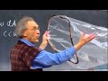
Delta Phi B by R we use an apparatus that allows a copper plate to swing back and forth draw a
magnetic field like a pendulum the plane in which the copperplate
swings is bad linked to the plane of the plate and normal to the direction of the magnetic field
as the copperplate enters the field the changing magnetic flux induces an EMF in the plate which in turn causes the free
electrons in the plate to move reducing circulating eddy currents note that the magnetic field is directed from
the North Pole to the South Pole of the magnet that provides the field when viewed from the north pole side of
the magnet the induced eddy current is counterclockwise as the plate enters the field
as the plate enters the magnetic field the external magnetic flux through the plate increases
hence by Lenz's long the induced current must provide effective magnetic poles on the plate that are repelled by the poles
of the magnet does here a north pole is induced over the surface of the plate facing the
North Pole of the magnet as the plate leaves the magnetic field the external magnetic flux through the plate
decreases hence again a spur lenses law the induced
current must provide a magnetic South Pole on the surface of the plate facing the North Pole of the magnet
this is quite opposite to the case when the plate enters the magnetic field the induced eddy current always produces
a retarding force FB when the plate enters or leaves the field this retarding force slows down the swinging
of the plate and eventually brings it to rest does the oscillations of the plate are
damped when rectangular slots are cut in the plate eddy currents and the
corresponding retarding force are greatly reduced this reduction in the retarding force is because the
rectangular cuts in the plate prevent the formation of large current loops hence the pendulum plate with holes or
slots reduces electromagnetic damping and the plate swings more freely let us now explore the uses of eddy
currents eddy currents are produced when a metal plate is subjected to a changing
magnetic field heats it hence these currents are unwanted in certain situations
reduction in the surface area of the plate helps introducing eddy currents in the metallic cores of transformers
electric motors and other such devices in which a coil is wound over a metallic core
eddy currents are minimized by using laminations of metal to make a metal call instead of using a single metal
piece the laminations are separated by an insulating material like lacquer
the plane of the laminations is arranged parallel to the magnetic field such that it cuts across the eddy current paths
this arrangement reduces the strength of the eddy currents since the dissipation of electric energy
into heat depends on the square of the strength of the electric current heat loss is substantially reduced
let us now study the applications of eddy currents strong electromagnets are situated above
the rails in some electrically pants trains when the electromagnets are activated
any currents induced in the wheels oppose the motion of the Train as there are no mechanical linkages
taking effect of the Train is smoked certain galvanometers have a fixed core made of a non-magnetic metallic material
when the coil oscillates the eddy currents generated in the core opposed the motion and bring the coil to rest
quickly induction furnace can be used to produce high temperatures and can be utilized to
prepare alloys by melting the Constituent metals a high-frequency alternating current is
passed through a coil which surrounds the metals to be melted the eddy currents generated in the
metals produce high temperatures sufficient to melt it the shiny metal disc in the analog type
electric parameter rotates due to eddy currents electric currents are induced in the
disk by magnetic fields produced by the sinusoidal varying currents in the coin consider a circuit consisting of a coin
having n number of turns connected to a source of EMF in which current can be delete with time
when the source current is in the direction shown the magnetic field directed as shown is set up inside the
COI when the source garden changes with time netic slugs through the coil also
changes and induces an EMF in the coil this phenomenon is called self induction the flux linkage through a coil of
interns is proportional to the current through the coil and is expressed as n Phi B is directly proportional to AI
replacing the proportionality symbol with a constant we get n Phi B is equal to L times the current ie where the
proportionality constant L is called the self inductance of the coil let this be equation 1
[Music] Elle is also called the coefficient of self induction of the coin
when the current in the circuit is varied the flux linked with the Corney changes
and an EMF is induced in the coil this means D by DT of n Phi be equals to L di by DT let this be equation 2
from Faraday's law photo coil of interns the self induced EMF E is equal to minus D by DT of n Phi B
let this be equation three comparing equations two and three we get the equation e is equal to minus L di by
DT that this be equation for [Music]
it is important to know that from lenses law the polarity of this induced EMF is such that it opposes the change in the
magnetic field from the source current [Music] even Saturdays equation concerns that
the self induced e-m-f opposes any change of current in the coil does this self-induced EMS is also
called back EMS [Music] the self induced e-m-f plays the role of
inertia it is the electromagnetic analog to mass in mechanics hence work needs to be performed to
establish a current in a circuit and it is stored as magnetic potential energy for a current ie at an instant in a
circuit the rate of work done is DW by DT is equal to modulus of e times I let this be equation 5
on substituting the magnitude of e from equation four in equation size and simplifying we get DW by DT is equal to
Li di by DT let this be equation six [Music]
the total amount of work done can be established by integrating equation 6 on both sides thus we get integral DW is
equal to integral over 0 to AI Li di [Music] dance the work done or energy consumed
in establishing a current in the circuit is w is equal to half Li square this expression is similar to the
expression for kinetic energy of a particle of mass M moving with velocity V which is given by E is equal to half
MV square this clearly shows that self-inductance l in electromagnetic induction is
analogous to mass m in mechanics thus self-inductance is the measure of electrical inertia it opposes the growth
and decay of the current in a circuit let us now calculate the self-inductance of a long solenoid let the length of the
solenoid be L the current through it bi the number of terms be in and its area of
cross-section be a let the number of turns per unit length of the solenoid be n which is equal to n
by L the magnetic field induced in the solenoid due to the current I is B is
equal to MU knot n I let this be equation seven here we neglect the edge effects of the
solenoid thus assuming the magnetic field in the solenoid to be uniform throughout
the magnetic flux is equal to the product of the magnetic field strength and the area
thus phi b is equal to b a let this be equation eight [Music]
using equation 7 and equation 8 we get the total flux linked with the solenoids is n CB is equal to n L into mu not ni
into a simplifying the expression we get n Phi B is equal to MU naught n square a Li
let this be equation 9 we have already established that M Phi B is equal to L times the current ie
barring this expression with equation nine and simplifying we get the value of L
as L is equal to mu naught n square e n let this be equation 10 this space in the coins of the solenoid
is filled with the material of magnetic permeability nu R then L is equal to mu R mu knot n square
al let this be equation 11 note that the self-inductance of the solenoid depends on the geometry and the
permeability of the medium an AC generator converts mechanical energy into electrical energy
in its simplest form an AC generator consists of a rectangular coil mounted on a rotor shaft
the coil is also referred to as the armature the coned is placed in a uniform
magnetic field the axis of the coil is normal to the direction of the magnetic field
the koi all the armature is mechanically rotated in the uniform magnetic field by some external means
let the number of turns in the coil be n the ends of the coil are connected to an external circuit by means of slip rings
and brushes the coin rotates inducing an EMF and current in its sense
the current induced in the koi is fed into external circuits through the slip rings that act as terminals to the
generator let us now find the expression for the EMF generated by an AC generator
consider the area vector e for the coil the area vector is normal to the plane of the coy
initially let the area vector lie in the direction of the magnetic field this implies that plane of the coil is
normal to the direction of the magnetic field let Peter be the angle between the area
vector E and the magnetic field B had to give an instant of time T when the coil is rotated at a constant
angular velocity Omega the value of Peter at the instant of time tea
is given by the equation beta is equal to Omega multiplied by time T let this be equation 1
the effective area of the coil which is linked with the magnetic field is e cos theta
from Equation one it is clear that the effective area of the coil is a time dependent function
in other words the rotation of the koi causes the magnetic flux through it to change
thereby inducing an EMF in the coil the flux induced in the coil and any instant of time is given by the equation
Phi B is equal to B a cos theta let this be equation 2 on substituting equation 1 in equation 2
and simplifying we get the equation Phi B is equal to B a cos Omega T
let this be equation three from Saturdays law the induced EMF for a coil of n turns rotating in a magnetic
field is given by E is equal to minus nd Phi B by DT the negative sign is in accordance with
lenses law on substituting the value of Phi B from equation three and simplifying we get e
is equal to minus n D by DT of B a cos Omega T strength of the magnetic field B and the
area of the coil a are constants the equation now transforms to e is equal to minus NBA D by DT of cos Omega
T from differential calculus we have D by DT of course Omega T is
equal to minus Omega sine Omega T hence the instantaneous value of the EMF e is equal to NBA Omega sine Omega T
let this be equation for note that NBA Omega is the maximum value of the EMF that occurs when the value of
sine Omega T is plus or minus one that is when theta is 90 degrees or 270 degrees this is because the
change of flux is the maximum at these two angles of the coin as the value of sine function varies
from plus 1 to minus 1 the sign all polarity of the EMF changes with time
accordingly the direction of the induced current changes periodically for this reason this current is called
an alternating current let us denote the maximum EMF MBA Omega as a note
then the instantaneous EMF is equal to e naught sine omega-t let this be equation five
we know that Omega is equal to two pi nu when you is the frequency of revolution of the generators coil
substituting the value of omega in equation 5 we get is equal to e naught sine 2 by nu T
let this be equation six dance equation six gives the expression for
the instantaneous value of the EMF earlier we have learned Oh an electric current is induced by the relative
motion between a closed coil and a magnet [Music]
electric currents can also be induced in a closed coil by causing a change in the magnetic flux produced by its relative
motion with another current carrying coil in its vicinity or by a flux change produced by the same coin
let us first understand the experimental setup that helps us demonstrate this phenomenon
the coil on the left is called a primary coil and is connected to a battery let the current in this coil be i1
on the right is called the secondary coil and it is connected to a galvanometer
the primary and the secondary coils are placed coaxial and an iron core runs along the axes of
the coils let B be the magnetic field strength due to the current in the primary coil
when the secondary coil is moved towards the primary coil the magnetic flux through the secondary coil increases
as a consequence of the increasing flux in the secondary coil the current induced in it increases as
it moves towards the primary coin let the current induced in this coid be I
when the secondary coil moves away from the primary coil the magnetic flux through the secondary coil reduces as a
consequence of the decreasing magnetic flux the current in the secondary coil decreases
the magnetic flux in the secondary coil phi b is directly proportional to the current
i in it the variations of the current in the secondary coil are directly proportional
to the variations in the magnetic flux does the rate of change of flux is directly proportional to the rate of
change of current let the number of terms in the secondary coil be in
hence the net flux change in the secondary coil and scipy is directly proportional to I
the term M Phi B is called flux linkage [Music] the constant of proportionality em
between the flux linkage and the current is called the mutual inductance of the coil
inductance is a scalar quantity and has the dimensions M L Square t power minus 2 e power minus 2
the SI unit of inductance is Henry named after the scientist Joseph Henry and is denoted by age
[Music] one Henry is equal to 1 Tesla meter square per ampere
so far we have explored the experimental setup with two coils of the same radius placed besides one another
let us now consider an example in which two coaxial solenoids induce current into one another
you consider to co-axial solenoids s1 and s2 all slend l-let the radius of the inner
solenoid s1 be r1 and the number of turns per unit length be n1 let the radius of the outer solenoid s
to be r2 and the number of turns per unit length by n2 let n1 and n2 be the total number of
turns in quois s1 and s2 dance we have N 1 is equal to n 1l and n 2 is equal to n2 n
when a current i2 is passed through the coil s to the magnetic flux is set up within the coil and this flux is linked
with the COI s one let us denote this magnetic flux by phi1 let this be the flux button of the coin
then the total flux linkage with solenoid s1 is n 1 Phi 1 equal to m1 2 I 2
let this be equation 1 m12 is called the mutual inductance of solenoid s1 with respect to solenoid s2
it is also referred to as the coefficient of mutual induction the magnetic flux is equal to the
product of the magnetic field strength into the area the magnetic field strength be - due to the current i2 in
solenoid s2 is given by B 2 equal to MU knot n - I - let this be equation 2 area of the coil in solenoid s 2a is
equal to PI R 1 square let this be equation three multiplying equations 2 & 3 we get the
value of the magnetic flux in the coil of solenoid s 1 as Phi 1 equal to MU knot n 2 I 2 into PI R 1 square
let this be equation for also we know that n1 is equal to n1 L
let this be equation size on multiplying equations 4 and 5 and simplifying the right-hand side
we get the expression n 1 Phi 1 equal to MU knot n 1 n 2 pi R 1 square L I 2 let this be equation six
equating the right-hand-side expressions of equation 6 and equation 1 and simplifying
we get em 1 2 is equal to mu not n 1 n 2 PI R 1 square L let this be equation 7 note that for these calculations
we neglected the edge effects and consider the magnetic field to be uniform throughout the length and width
of the solenoid s2 also solenoids of equal lengths were chosen
this is a good approximation keeping in mind that the solenoid is long incline L is much greater than R two
[Music] let us now consider the case in which current i1 is passed through the
solenoid s1 this current produces magnetic which is also linked with the solenoid
s2 let the magnetic flux Burton linked with solenoid s to be Phi 2
then the total flux linkage with solenoid s 2 is n 2 Phi 2 is equal to M 2 1 i1
let this be equation eight m21 is called the mutual inductance of solenoid s 2 with respect to solenoid s
1 it is also referred to as the coefficient of mutual induction
the magnetic flux is equal to the product of the magnetic field strength into the area the magnetic field b 1 due
to the current i1 in solenoid s 1 is given by B 1 is equal to MU knot n 1 i1 let this be equation 9
[Music] area of the coil in solenoid s1 e is equal to PI add 1 square
let this be equation 10 here we assume the flux due to current i1 through s1 is completely consigned to
the solenoid s1 only this is because the solenoids are very long
on multiplying equations nine and ten we obtain the magnetic flux per turn through the coil of solenoid s 2 as Phi
2 equal to mu knot n 1 I 1 into PI R 1 square let this be equation 11
we also know that n 2 is equal to n 2 l that is the equation 12 on multiplying equations 11 and 12 and simplifying the
right-hand side we get the equation n 2 Phi 2 is equal to MU naught n 1 n 2 pi R 1 square L I 1
let this be equation 13 equating the right hand side of equation 13 and equation 8 and simplifying we get
the expression M 2 1 is equal to MU naught n 1 n 2 pi R 1 square L let this be equation 40 comparing equation 7 and
14 we get M 1 2 is equal to M 2 1 let M 1 2 is equal to M 2 1 be equal to M which is equal to MU naught and 1 n 2 pi
R 1 square L note that the mutual inductance is
neither dependent on the current nor the magnetics nuts it is dependent on the geometrical
dimensions of the solenoid this expression is true when the medium within the solenoids is air
if the medium within the solenoids has relative permeability mu R then M is equal to mu naught mu R n 1 n 2 pi R 1
square L [Music]
this equality m12 is equal to m2 one moon's good for long coaxial solenoids and is far more general
even though the in a solenoid s1 is much smaller than the outer solenoid s2 calculation of flux linkage within a
solenoid is possible as it is effectively immersed in the uniform magnetic field due to the current
through the outer solenoid does calculation of mutual inductance m12 is easy
in this case it is difficult to find the flux linkage without a solenoid due to the current through the inner solenoid
this is because the magnetic field due to the inner solenoid would vary across the length as well as the cross section
of the outer solenoid does calculation of mutual inductance m21 becomes difficult
let us now take a look at how a change of current effects mutual inductance [Music]
let us consider an experimental setup in which there is a coin see one that is connected to a galvanometer G
and another koi see two connected to a battery EMF is induced in coil c1 wherever there
is any change in current through coil c2 let's find one be the flux through coil see one of N 1 turns when current in
coil C 2 is i2 a 10-1 v 1 equal to M I to the rate of change of current is equal to the rate
of change of flux this means that DN 1 Phi 1 by DT is equal to DM i 2 by DT
the EMF induced in coil C 1 is given by e 1 is equal to minus T n1 Phi 1 by DT this implies that e1 is equal to minus M
di2 by DT remember only flux and current change hence M is a constant
this equation shows letter veering current in a coin can induce EMS in a neighboring coin
let us now solve an example to reinforce our understanding of mutual inductance a current-i passes through the outer
ring of two coplanar concentric loops of radii r1 and r2 our one is much greater than R 2
what is the mutual inductance between the two loops the magnetic field induced by a
current-i at the center of the ring of radius r1 is B 1 equal to MU knot I by 2 r1
the flux through the ring of radius r2 is given by Phi 2 1 equal to B 1 e 2 this implies that Phi 2 1 is equal to MU
knot I by 2 R 1 into PI R 2 square mutual inductance M is given by sight to one by I on substituting the value of
side to one and simplifying we get the value of mutual inductance as mu not PI R 2 square by 2 R 1
[Music] [Applause] [Music]
[Applause] [Music] [Applause]
[Music] you
Electromagnetic induction is the process by which a changing magnetic field induces an electric current in a conductor. This phenomenon occurs when there is relative motion between a magnet and a coil or between two coils, as demonstrated in Faraday's experiments. The induced electromotive force (EMF) is proportional to the rate of change of magnetic flux through the coil.
Faraday's Law states that the induced EMF in a coil is equal to the negative rate of change of magnetic flux through it, expressed as E = -dΦB/dt. Lenz's Law complements this by stating that the direction of the induced EMF opposes the change in magnetic flux that produced it, ensuring energy conservation and preventing perpetual motion.
Self-inductance occurs when a coil induces an EMF in itself due to a change in current, while mutual inductance involves one coil inducing EMF in a nearby coil due to a change in current in the first coil. The self-inductance is represented as L, and the mutual inductance is represented as M, with their respective formulas governing the induced EMF.
Eddy currents are loops of electric current induced within conductors exposed to changing magnetic fields, leading to energy loss as heat. These currents can reduce the efficiency of electrical devices, such as transformers and motors, which is why techniques like laminating cores are used to minimize their impact.
An AC generator converts mechanical energy into electrical energy by rotating a coil within a magnetic field, producing alternating EMF. The induced EMF can be calculated using the formula E = N·B·A·ω·sin(ωt), where N is the number of turns, B is the magnetic field strength, A is the area of the coil, and ω is the angular velocity.
Electromagnetic induction principles are applied in various technologies, including electric generators, transformers, induction heating, and electromagnetic braking systems. These applications leverage the ability to convert mechanical energy into electrical energy and vice versa, showcasing the versatility of induction in modern devices.
To deepen your understanding of electromagnetic induction, consider reviewing related resources such as 'Understanding Faraday's Law and Lenz's Law' and 'Understanding Inductors in Circuit Theory.' These guides provide detailed explanations and examples that can enhance your grasp of the subject.
Heads up!
This summary and transcript were automatically generated using AI with the Free YouTube Transcript Summary Tool by LunaNotes.
Generate a summary for freeRelated Summaries
Understanding Faraday's Law and Lenz's Law: A Comprehensive Guide
Explore Faraday's law, Lenz's law, inductors, and electricity generation in our detailed guide for physics enthusiasts.
Understanding Faraday's Law and Electromagnetic Induction: Key Physics Concepts Explained
Explore the fundamental principles of Faraday's Law and electromagnetic induction through detailed explanations and engaging demonstrations. This summary covers the relationship between changing magnetic fields and induced electromotive force (EMF), Lenz's Law, the significance of magnetic flux, and the non-intuitive nature of non-conservative electric fields in circuits.
Understanding Ampere's Law and Its Application in Electromagnetism
Explore the fundamentals of Ampere's law, the behavior of magnetic fields in loops, and their implications in real-world phenomena.
Comprehensive Guide to Magnetism: Magnetic Fields, Forces, and Applications
Explore the fundamentals of magnetism, including magnetic fields created by bar magnets and current-carrying wires, magnetic forces on charges and loops, and practical calculations like forces between wires and torque on coils. Understand key principles and equations with detailed examples and problem-solving techniques.
Understanding Magnetism: Forces, Currents, and Magnetic Fields
Discover the principles of magnetism, how currents create magnetic fields, and the forces involved, explained in simple terms.
Most Viewed Summaries

A Comprehensive Guide to Using Stable Diffusion Forge UI
Explore the Stable Diffusion Forge UI, customizable settings, models, and more to enhance your image generation experience.

Kolonyalismo at Imperyalismo: Ang Kasaysayan ng Pagsakop sa Pilipinas
Tuklasin ang kasaysayan ng kolonyalismo at imperyalismo sa Pilipinas sa pamamagitan ni Ferdinand Magellan.

Mastering Inpainting with Stable Diffusion: Fix Mistakes and Enhance Your Images
Learn to fix mistakes and enhance images with Stable Diffusion's inpainting features effectively.

Pamamaraan at Patakarang Kolonyal ng mga Espanyol sa Pilipinas
Tuklasin ang mga pamamaraan at patakaran ng mga Espanyol sa Pilipinas, at ang epekto nito sa mga Pilipino.

How to Install and Configure Forge: A New Stable Diffusion Web UI
Learn to install and configure the new Forge web UI for Stable Diffusion, with tips on models and settings.

If you found this summary useful, consider buying us a coffee. It would help us a lot!