
Course Overview: Mastering Finite Element Analysis (FEA) - Your Gateway to Engineering Simulation Excellence i️
This certified training course delivers a thorough introduction to Finite Element Analysis (FEA), a cornerstone numerical technique for modern engineering problem-solving. The course is structured into six comprehensive chapters, covering everything from fundamental principles to industry applications and career opportunities.
Chapter 1: Fundamentals of Finite Element Analysis 📐
The Need for FEA in Engineering
Why use FEA? Engineering problems often involve complex shapes, boundary conditions, and material behaviors that classical analytical methods (like strength of materials) cannot solve. FEA bridges this gap by providing approximate numerical solutions.
The Three Solution Methods:
- Analytical Method: Closed-form equations; 100% accurate but limited to simple geometries.
- Numerical Method (FEA): Mathematical representation of physical problems; handles complex real-life scenarios even without a physical prototype.
- Experimental Method: Actual lab measurements; accurate but time-consuming, costly, and requires multiple prototypes.
Types of FEA Analysis
| Analysis Type | Key Characteristics | | :--- | :--- | | Linear Static | Constant load, linear force-displacement, constant material properties, no geometry change | | Nonlinear | Incremental loading, large deformations, nonlinear material properties (e.g., plasticity) | | Dynamic | Time-varying loads; includes modal, frequency response, and vibration analysis | | Buckling | Predicts collapse load for slender structures | | Thermal | Determines stresses from temperature changes | | Fatigue | Predicts component life under cyclic loading | | Crash | Simulates collisions (e.g., automotive crash testing) |
The Four Stages of FEA Problem Solving
- CAD Modeling: Build or import the 3D geometry.
- Pre-processing:
- Discretization (Meshing): Divide the domain into sub-domains (elements).
- Define material properties (Young's modulus, Poisson's ratio, etc.).
- Define sectional properties (thickness for 2D, area for 1D).
- Apply boundary conditions and loads.
- Solution: The solver assembles and solves the system of equations (KU = F).
- Post-processing: Review and validate results (stress, strain, displacement). Iterate back to step 1 if needed.
Core Concept: The Stiffness Matrix (K)
The fundamental equation for static analysis is {K}{U} = {F}, where:
- {K}: Stiffness Matrix (contains geometry and material behavior information).
- {U}: Nodal Displacement Vector (the unknown).
- {F}: Nodal Force Vector (known).
The stiffness matrix is symmetric and singular before boundary conditions are applied, meaning it cannot be inverted. Boundary conditions are required to remove rigid body motion and make the matrix solvable.
Nodes vs. Elements
- Node: A coordinate location in space where degrees of freedom (DOF) and physical properties (displacement, stress) are calculated.
- Element: A mathematical entity that interpolates the physical properties between nodes. Accuracy increases with a higher number of nodes.
Types of Elements:
- 1D: Line elements (beams, trusses, springs).
- 2D: Planar elements (triangles, quadrilaterals) with thickness.
- 3D: Volume elements (tetrahedrons, hexahedrons). Quadrilateral/hexahedral elements typically offer higher accuracy.
Chapter 2: Inputs Needed for FEA Analysis 📝
Performing an accurate simulation requires these key inputs:
- Geometry: 3D CAD model.
- Sectional Properties: Required for 1D elements (area, moment of inertia) and 2D elements (thickness).
- Material Properties:
- Linear: Young's modulus, Poisson's ratio.
- Nonlinear: Adds yield stress, plastic strain.
- Dynamic: Adds density.
- Thermal: Adds coefficient of thermal expansion.
- Boundary Conditions: Fixed, pinned, or roller supports to constrain the model.
- Loading: Forces, pressures, moments, thermal loads, or inertial loads.
- Test Data: Used for validation; +/-10% error is often considered acceptable.
Chapter 3: Best Practices in FEA Simulation ✅
- Match Real-World Conditions: Your simulation setup should closely mimic the actual physical scenario.
- Verify Material Properties: The accuracy of your results depends heavily on correct material data.
- Avoid Stress Singularities: Do not apply loads or constraints at single nodes or very small edges.
- Use Engineering Judgment: Interpret results critically, not as absolute facts.
- Choose the Right Formulation: Linear vs. nonlinear, element type (quadrilateral vs. triangular).
- Ensure Convergence: Refine the mesh until results stabilize.
Chapter 4: Current Trends and Growth in FEA 🚀
- Dominant Industries: Automotive held the dominant market share in 2019; the Aerospace sector is expected to see the highest growth.
- Regional Growth: Asia Pacific and South America are emerging as lucrative markets for CAE software.
- Key Market Players: Ansys, EXA Corporation, MSC Software, ESI Group.
- Technological Drivers: Cloud-based systems and faster, more powerful solvers are revolutionizing the FEA landscape.
Chapter 5: Software Tools for FEA 🛠️
Popular industry-standard FEA software includes:
| Software | Type | | :--- | :--- | | Abaqus | General-purpose (Standard & Explicit) | | Ansys | General-purpose & multiphysics , see our Complete ANSYS Fluent Tutorial: NACA 2412 Airfoil Simulation and Analysis for a practical example | | HyperMesh (Altair) | High-end meshing & pre-processing | | Nastran | Structural, dynamic analysis | | LS-DYNA | Explicit dynamics, crash analysis | | SolidWorks Simulation | Integrated CAD/CAE |
Chapter 6: Work Opportunities and Career Path 💼
Industries Using FEA
- Aerospace (Boeing, Airbus)
- Automotive (Chrysler, Caterpillar)
- Off-Highway & Construction
- Medical Devices & Biomedical Engineering
- Consumer Electronics (Microsoft, Amazon)
- Civil & Electrical Engineering
- Virtual Engineering (e.g., Facebook)
Critical Skills for an FEA Engineer
- Solid Theoretical Knowledge: Understanding the mathematics and physics behind the solver (nodes, elements, PDEs, shape functions).
- Good Modeling Practices: Ability to choose the right element type, connections, and mesh control for the problem.
- Software Proficiency: Mastery of at least one major FEA package (learned on the job).
- Engineering Fundamentals: Strong foundation in Statics, Mechanics of Materials, Dynamics, Machine Design, and Engineering Graphics , covered in our Comprehensive Guide to Building Engineering and AutoCAD Fundamentals.
hey guys and welcome to the full course on introduction to finite element analysis your gateway to mastering one
of the most powerful techniques in engineering analysis and problem solving this is a certified course so make sure
to fill out the form in the description after completing the session to claim your certificate you can proudly share
your achievement on LinkedIn to Showcase your new skills at skill link we are dedicated to offering Advanced industry
relevant engineering courses crafted by industry experts don't forget to subscribe to our channel for more
insightful tutorials and updates on engineering tools and techniques hit the Subscribe button and stay tuned here's a
brief overview of what we will cover in this training video in the first chapter we will introduce you to the
fundamentals of finite element analysis you will learn about its purpose and significance in solving engineering
problems especially when analytical or experimental methods fall short we will discuss the different types of analyses
carried out in FAA including linear nonlinear Dynamic and thermal simulations this chapter will also cover
the stages of solving FBA problems from CAD modeling to results validation along with key Concepts like the equation of
motion and stiffness Matrix in the second chapter we will discuss the inputs needed to perform an FP analysis
you will learn about gometry requirements material properties boundary conditions and loading we will
also guide you through the basic basic process including meshing defining materials and sectional properties
solving equations and interpreting results in the third chapter we will explore the best practices in FAA
modeling and simulation this chapter will focus on how to set up simulations that mimic real world conditions verify
material properties avoid stress singularities and ensure convergence of results these practices will help you
achieve accurate and reliable simulations in the fourth chapter we will introduce
you to the current trends and growth opportunities in FAA we will discuss the increasing demand for FAA skills in
Industries like Aerospace Automotive construction and consumer electronics you will also learn about how
advancements in cloud-based systems and faster solvers are revolutionizing the FAA
landscape in the fifth chapter we will discuss the software tools used in FAA including industry favorites like Abacus
aners and hypermesh you will gain insights into how these tools are utilized in various domains to solve
real world engineering challenges in the sixth chapter we will explore the work opportunities and
industries for FAA Engineers you will discover how FAA is applied across sectors like Automotive Aerospace
biomedical and virtual engineering this chapter also highlights the critical skills you need to excel in this field
such as strong theoretical knowledge modeling expertise and proficiency with an FAA software thank you for joining us
we are thrilled to have you on this Learning Journey make sure to subscribe to our channel for more updates and
detailed tutorials complete the training earn your certificate and share your achievement on LinkedIn let's get
started with introduction to finite element analysis and unlock your potential in this exciting domain
welcome to this webinar and today we are going to have a webinar on uh the topic of basic introduction to FAA so uh in
this basically the uh main objective or a main agenda of this will be to give you some brief idea uh of the FEA like
um brief idea about the FAA and this basically uh this will divide uh this webinar is divided into three sessions
so first session is Introduction to FAA in which I'm going to cover introduction to finite element analysis
type of analysis which are carried out in the FAA stages to perform any FAA problem we what we need what input we
need to perform that FAA problem basic process summary and then basic key Concepts like uh equation of motion or
stiffness Matrix how it get formed and how we can apply the stiffness Matrix while calculating doing the FAA
calculations and then I'm also going to share best practices uh for modeling or simulating your FAA in section two is a
opportunities for fa Engineers so there I'm going to discuss about current trends and growth opportunities for FAA
engineers then what softwares you should learn in the FAA or what are the current uh softwares in the market I'll give you
that information then uh what are the work opportunities and interest days in which we are widely using the Fe
nowadays and then I'll also share some critical skills required to get into this domain so that uh when you come
here or uh when you start exploring this field you will come with some uh background or some um basic
prerequisites and then the last will be the question answer session as uh over there if you have any doubt you can just
uh drop it into the chart box and then at the end of the seminar I'll try to address uh those queries so this is how
our uh big basic webinar is going to look today and Main objective of this webinar is to provide the basic overview
process of the FAA uh so when you complete this webinar you will have some idea about the FAA process what is FAA
and how we carried out that then basic key concepts of the FEA uh so if you start studying the feia this will uh
definitely help you then provide the opportunities uh information about the opportunities for FAA Engineers uh and
then critical skills required to succeed in the as a FAA Engineers so all this my main objective is to provide you all
these insights so uh so that you will have some good learning about the FEA today so let's begin with our section
one that is Introduction to FEA okay in first section first of all I want to uh
basically tell you that why we need FAA FAA why we need FAA so in engineering problem or as a mechanical engineer our
Duty or when we are into core mechanical thing our main objective is to design the component to design the equipment so
that it can sustain under given load conditions with without occurring any kind of uh failure or if there is a
failure we should be aware that how much load it will take before it will actually fail so that information we can
get uh when we want to have that information we can get that information by using solution using either strength
of material or theory of elasti are normally accomplished for the regions and loadings with relatively simple
geometry we can get that information from the strength of material but that is very relatively we can use
that for very simple applications because that is a formula bested and we have
uh that is a basically simple uh geometry we can say those formulas are applicable basically so when uh in many
applications involve cases with complex shapes and boundary conditions and material Behavior therefore we can say
that in uh theoretically we can solve simple problem but practically when we come uh in in the Practical component
design world we have the different scenarios different complex uh component is there complex geometries are there
the complex uh boundary conditions and loading conditions are there and we are we want to uh predicted results for all
these different scenarios and at that time it is uh at that time it is kind of difficult or uh let's say not
kind of ult or we can say impossible to com uh do it with the uh when we use the analytical method and therefore we can
say that the Gap exists between uh what is needed in the application and what can be solved by analytical close form
methods so and this this Gap actually uh leads to the development of several numerical methods and uh finite element
element method or finite element analysis is one of the numerical method method so here is a brief introduction
of why we need FEA or what is the need of FEA basically uh to summarize we can say
that to solve any engineering problem there are three types of method so first is analytic analytical method second one
is numerical method and third one is experimental method and each of this method has its own uh positives and
negatives so if you go with the analytical method analy analytical method is a classical approach where we
are using the closed form equation to solve any kind of uh problem and uh where you know the error is zero because
you are 100% accurate you have the um geometry you have the formulas and you're just solving it so that is 100%
accurate but that is only valid for simple geometries because for complex geometries you cannot do those complex
calculations by hand [Music] second method is numerical method so in
this numerical methods what we do is it's a mathematical representation of physical problem then it's a approximate
assumptions mode it is applicable even if physical prototype is not available so when we say it is approximate
assumptions mode it means that we uh there are assumptions which we uh take into the considerations like material or
boundary conditions but those assumptions are very close to the real life problems so in that case though we
have some assumptions but still we can trust those results uh then it applicable if uh physical prototype is
not available we can have the cad model and we can solve that we don't need any physical prototype for that then solve
real life complicated problems and any kind of scenario actually we can uh simulate with the numerical method but
the results cannot blindly uh trusted we must verify with the experimental methods or with the hand calculations
for the uh for the validation so we can say it is it has very wide scope but we also uh cannot
blindly trust it but we uh can get the solutions for a lot of uh problems by using numerical method then the third
method is uh experimental method in experimental me method is a actual measurement method which we do in the
lab then but it is very time consuming and it needs actual setup it needs a lot of uh lot of prototypes we need at least
three to five prototypes we have to test before we actually uh say the results are looking good or results are
trustworthy we have to at least go for three to five prototypes and it involves a lot of cost also as well as time and
uh basically the biggest disadvantage I can say for the experimental method only experimental method if we trust that we
need lot of if we want to go with lot of design iteration then it takes a lot of time to complete that prototype and uh
which involves to cost as well as time so uh experimental method is there but it is very time consuming so if we
compare all these three methods so out of that I numerical method is one of the best method which we are using nowadays
to solve any engineering mechanic engineering problem
then what are the different numerical methods we are having uh nowadays so we are having finite element method
boundary element method finite volume method and finite difference method in finite element method we find the
approximate solutions to the boundary volum problems for partial differential equations we actually here try to solve
the partial differential equations in finite element analysis then uh in boundary element method we uh
analysis is done on the only on the outer surface of the body then in the finite volume method it
is mainly suitable for computational fluid dynamics and finite difference method is in that method we solve the
differential equations not the differential equations so if we compare this foral method we can say that uh in
boundary element me we can we are just solving it for the outer domain so what is happening inside the body have the
visibility by using the boundary element method so over there we get the restriction for that method volume
method is mainly used for the computational FL Dynamics so uh if you have the structural problems you cannot
go with that method then finite difference method here you actually solve the differential equations and it
is very difficult to solve the differential equation for complex geometry for simple geometry you can do
that but for complex geometry it is really difficult so uh the finite element method which is basically depend
on the solving the partial differential equation is the best method out of all these four which can give you most
accurate results so and that's why finite limit method is so widely we are using in the industry so for fluid
dynamics problem we use the uh fvm that is finite volume method and for structure related problems for thermal
related problem we go with the finite element method as those are the methods which will give you the best results for
any mechanical problem then uh now let's dig more into what is
finite element analysis so the finite element analysis is a
numerical method for solving a problem of engineering and mathematical physics for given structure the behavior
of the structure can be described by governing partial governing differential equations to approximately predict the
behavior of the structure it is necessary to find a solution of governing part differential equations so
basically finite element method is based on the discretization of the actual domain so
what we we can summarize in a simple term is that that in a uh a problem domain is a collection of subdomains
like uh if we have the big component or big domain we are going to divide that or discretize that
into number of subdomains called elements we're going to solve the problem at each subdomain then assemble
the assemble element to find out the global solution then assemble those equations Elemental level equations to
find the global solution solution is guaranted to converge uh to the correct solution if proper Theory element
formulation and solution procedure are followed so uh this is basically uh FAA that we have for continuous problem we
have um a number of uh particles we have a number of particles like infinite degrees of freedom we can say it is not
possible to solve those infinite number of solutions so what we do with the discretization we are cutting the
geometry into number of pieces we're trying to solve those uh for that subdomain we assemble those subdomain
together to define the entire geometry uh and then uh we solve the unknown basically uh which uh we need
from the [Music] simulation advantages of f analysis is
product performance basically how is for the given load how your product is going to perform how the stresses are looking
how uh the strain is how is the displacement is so uh basically validate Your Design reduce the raw material if
you find the stresses are too stresses are very low for the given material we can definitely play with the thickness
or other parameters so that we can cut down on the material and we can save the cost over there ensure optimal design
best possible design by using the FAA we can we can give the optimal design then uh we can use this method for
verification purpose it reduces manual testing and prototyping type because it is cut down on number of iterations
design iterations which you will actually need to build the Prototype so over there you're saving lot of time and
cost and you are giving the quick Solution by using this method does what if
scenario so you can uh study different type of scenarios by using the final element analysis method and you can
fullprof your design by uh by applying those different scenarios and seeing the results for those scenarios and validate
your component is going to sustain for those particular scenarios also and it shorten the design time absolutely it
shorten the design time no doubt about it so these are the advantages and they are very
uh promising advantages and because of that we can save a lot of time lot of cause and a lot of efforts also so no
definitely and that's why nowadays we are using uh final element analysis method so widely in the industry then uh
type of analysis which we carried out are generally linear analysis nonlinear analysis Dynamic analysis buckling
analysis thermal analysis fatigue analysis crash analysis and NV analysis so I would like to give a brief summary
about each of this so in linear static analysis basically what we consider is that our load whatever we are applying
is constant throughout the time it is not varying with respect to Time Force versus displacement PL if you plot Force
versus displacement it has a linear curve linear graph for Force versus displacement as a linear relation
between them uh what is what does it mean is like if uh for one newton Force if you're getting 2 mm displacement then
for two Newton Force you're are going to get 4 mm displacement that is a linear um linearly related Force versus
displacement ratio then we can assume that all the uh it has all the linear properties like it constant it has
material properties which are constant throughout the simulation it geometry is not changing uh it geometry is not
changing and it is not going under um any nonlinearity uh in this simulation so it
is kind of very simple analysis uh which we assume it is very easy to solve basically for the software and uh over
here we can also apply the um superposition method and um the results can be scalable actually uh so the
results can be scalable and superposition method we can apply over here so uh this is basically linear
static analysis but it is only valid for uh where you have the constant material properties and where you have the um not
complex contacts are there no nonlinear it is present over basically over there for that kind of scenario linear
analysis or linear static analysis we can say is very helpful then for nonlinear analysis uh
nonlinear analysis is the analysis in which basically the we can say that uh load is
constant but load what we are applying is incremental in the software then we can
say that Force versus displacement ratio is not linear in this case it is nonlinear we are going under geometry is
going under large deformation so because it is going under large deformation we have to consider the geometrical
nonlinearities the changing shape shape of the geometry we have to consider that when we are doing the FAA then we also
here we also consider the nonlinear material properties uh so we can say that we have to specify the material
Behavior after uh once it crosses the yeld Point what is the behavior that behavior we have to Define when we are
saying nonlinear material properties in the material like we have to specify the um I will come to that but uh it like
plastic strain and uh yield strength we have to specify for nonlinear material proper nonl analysis and then over here
we also consider the boundary nonlinear means uh if the components are changing their contacts we are considering all
those effects into this analysis so in this analysis you can find out lot of conversion issues um and a lot of skill
required to perform nonlinear simulation then Dynamic simulation is basically um where load is going to vary with respect
to time and here the type of simulations We performed is model simulation frequency response simulation uh and
basically we also study in different type of vibrations in Dynamic analysis then buckling analysis is one thermal
analysis where we want to find out the stresses occurred in the component when the temperature is changing so what are
the effect of the temperature changes on the uh stresses that study we do using the thermal analysis then uh basically
thermal analysis is useful uh useful for uh core engine components it is very very useful in alysis then uh for large
data centers uh enclosures I must say thermal analysis is a very very important analysis
[Music] then ftig analysis ftig analysis is generally for uh to find out the life
cycle um for rotating components ftic analysis is very useful then uh crash analysis for car collision generally we
go for crash analysis then enas analysis so and there are many more but these are the most popular and most uh used
analysis which we do uh in the f then uh now as we have little bit idea about why we do FAA or what is FAA I
going to go more details that stages of FEA so uh there are basically I say four stages of FEA like
we need a cad model to build the FAA we have to do the pre-processing we're going to solve the solution and then the
post processing these are the four main stages to perform any F simulation so CAD data we have to take from the uh
CAD Department then uh pre-processing is the one uh cat data is like geometry we are
having our geometry to perform the FEI then we in pre-processing first step is that discretization that is a mission we
have to divide that domain into number of subdomain so that we can defi Define our problem more properly so that's why
our uh and we can solve our partial differential equations and that's why discretization is very important step in
the pre-process uh in the FAA if you reprocessing then apply the boundary conditions before applying the boundary
condition you have to specify the properties like um so what are the sectional properties
for this component what are the material properties you have to define the them then you will go for the boundary
conditions and loading and then solution what type of solution you want uh that is there you have to specify the uh load
step and you have to uh you have to specify the step basically where you will Define what type of analysis I want
to do and uh what will be the output I'm interested in all that data you will provide over there then after that we
will go for the solution where software will actually run the program at the back end and try to solve all those
partial differential equations and give you the result for entire domain in the form of displacement
stresses and strength then in the postprocessing we are going to review the results validate the
results and if we have if we are finding the stresses are too high or we are not uh the results are not satisfactory and
we have to do some design changes then again again you will go back uh to the CAD cycle and again you have to go for
the C modification again pre-processing so this cycle keeps repeating unless and until you find
the you find the correct [Music]
solution then in input needed to perform input needed to perform fa so here I'm going going to tell you more in
detail about uh geometry that is what we need is a 3D CAD model in the sectional
properties I I will need for the 1D beam element I'm going to for 1D element like beam Element Bar element Tres element
spring element what I will need is their sectional properties to define the component or to Define that in a
complete uh in a complete manner so that I can do the calculations on that if I'm having the beam 1 beam element so for
that I will need the area as a sectional property sometime moment of enertia I I will need to Define that element for
spring I will need the spring stiffness then for 2D element I will need the thickness because I'm having the 2D
element I'm having the surface but I will need the thickness to Define that geometry completely into the fa domain
so that it will do the calculations which I need for 3D element you don't need to do any sectional properties
because 3D element it's is a uh it's completely defining the geometry so for that you don't need any kind of
sectional properties but after the geometry you will need the sectional properties and these sectional
properties you can take from the cad and it is always good to verify that with the um your CAD department and
understand what your considerations are correct or not then the third one is material in the material material for
linear analysis I'm going we have to use the young modulus and poison ratio these are the two main material properties
basically when we give this two material properties other properties it will calculate automatically based on
the based on the equations other equations and relations we can find out uh other properties but uh basic need is
Young modelist and poison ratio then nonlinear uh analysis we have to uh y modulus poison ratio yield stress and
plastic stren we have to Define for the dynamic analysis you will need along with the dung models and poisons ratio
you will also need the density because in Dynamic analysis you are also going to uh consider the effect of inertia and
for that density is important uh so we have to specify the density when we are going for dynamic analysis and then the
thermal analysis basic is coefficient of thermal expansion and for the boundary conditions you will specify the
temperatures now when we say we will need the load also once you do uh the first three steps after that you have to
Define what load is going to apply on the on the structure then uh for that load can say that structural loads are
forces applied to the part or assembly during the operation such loads cause stresses deformation and displacement in
the component so we have to basically study with that applied load what are the stresses deformation and uh Strain
coming in the component in the given component basically uh and the type of loads can be inertial inertial load
structural load structural supports and thermal load these are the loads which we have to specify then boundary
conditions are also very important and the test data the boundary conditions are the most important uh actually uh
the thing in this uh because if we miss to give the boundary conditions we can uh end it with a lot of numerical errors
uh while solving the simulation basically uh when we Sol the linear and nonlinear static simulation at that time
you will end up with lot of Errors if you miss to give the bounding conditions in the boundary conditions we are
basically defining the type of supports uh Which object will have it can be a fixed support it can be a support
constraint it can be a pin support or r or roller support but we have to Define whatever is the support we have to
Define that support um and apply the load so that in that way we are actually simulating that uh actual behavior of
the case then we will need the test data it is always good to have test data for validation purpose because when you will
get your fa results it's always good to cross check with the test data so that uh you will be assured that whatever
calculations you are doing are correct correct or whatever assumptions you have considered are correct and here also we
say that with the test data or with the hand calculation there can be plusus 10% error is acceptable uh
but but it is always good to have less error uh than that so these are the uh basic input
requirement for the FAA then I'll go with the basic process summary for the FAA
so in that uh now this is kind of technical so in that what first step is that domain discretization that is what
we are doing as a Ming then select the element type here we are defining the shape function and we are defining how
that element is going to behave or what type of behavior that element is going to capture uh by selecting the type of
element then we are defining the geometry as well as the behavior actually by selecting the element then
we are uh deriving the element equations uh the third step is deriving the element equation first step is
assemble those element equation in the form of global system so in this we are after that we are going to f uh solve
the stiffness Matrix like uh this equation we can say this is the equation for static analysis like KU is equal to
F is the uh static analysis equation which we uh SOL at the back end so K is nothing but the stiffness property of
the Matrix U is the nodal displacement Vector f is the noal force Vector the fifth step will be incorporate boundary
condition boundary and initial condition that will be our fifth step then solve the assembled equations
uh solve the system of equation for unknown noal and then the displacement uh first of all we will solve it for the
uh noal displacement and then we are go from the noal displacement we will go with the strain and from the St strain
relationship we will find out for the stress so that will be our sequence actually in the back end so uh the logic
behind fa is this why uh how the actually software will solve this equation is uh this is the summary form
[Music] so uh I also want to tell you in brief that when I
say I want to tell you the steps like uh again in another words like first step will be the discretization second step
will be the defining the global displacement Vector U that Define the element properties and material
properties fourth will be compute the element stiffness Matrix fifth will be compute the singular global stiffness
Matrix six sixth point will be Define the boundary conditions to remove all free body motions because when we will
have the stiffness Matrix it will be without boundary condition so what does it mean that it will have the rigid body
motion that you don't have any constraint so when we are applying the load the body will move as a rigid body
motion with the rigid body without any deformation or without any strain so and in that case software cannot solve that
equation then compute the non- singular Global stiffness Matrix then Define the external load and compute it solve the
static equilibrium equations compute the displacement uh compute the compute the displacement vector and after that
compute the other V uh other outputs like stress and strain and uh contact pressure and all other things you can
definitely go ahead and uh use that then here I want to uh explain you that basically what is stiffness Matrix when
we go for stiffness Matrix what is stiffness Matrix or how that stiffness Matrix is going to solve your equation
so let's consider this is a spring the stiffness matric constraint the geometry and material Behavior information that
indicate the resistance of the element to deformation when subjected to the Loading so if I how we form the sience
Matrix here I want to explain you that so consider this is a spring it has the point one and two we can consider that
as a node one and node two these two nodes we are going to attach with the spring this is our element basically
which has the two nodes then we are applying the force F1 at node one we are applying the force FS2 at node 2 because
of force one we are getting the U1 displacement and because the force 2 we are getting the U2 displacement so if we
solve the equilibrium at node one the equation what we will get is fub1 is equal to ku1 minus ku2 and at note two
the equation we will get is FS2 is equal to minus ku1 plus ku2 if we go ahead and form the Matrix with this equilibrium
equations we can also write in The Matrix form for easy solution so we are going to write in The Matrix form so in
that case we will have the K as a stiffness Matrix we will have the displacement Matrix we will have the
force vectors nodal Force Vector so that is the Matrix will look like K minus KU minus k k then U1 U2 is equal to fub1
and FS2 this will and this will form KU is equal to F is the equation basically or is the Matrix which we are going to
solve solve uh for the linear analysis basically this equation is only valid for static analysis not uh linear but uh
static analysis like linear as well as nonlinear static analysis this is the equation but the difference here is that
for linear analysis the stiffness is going to be constant throughout the simulation and for nonlinear analysis
the stiffness is going to change continuously and for that you have to um with every increment you have to solve
the stiff Matrix for nonlinear simulation then for stiffness Matrix I want to give you more information like
how we arrive with our sness Matrix or what is the sness Matrix means for so dis we know that deflection or
displacement is equal to PL upon AE that is force uh into length divided by area into y modulus then if we we also know
that uh K is nothing but Force required to produce unit displacement so if we write P ided by D what we will get is
that AE by L so this a by L we are going to put in this uh stiffness Matrix basically
instead of K we are going to write AE into L because when we are having the FEA we know the material properties and
we know the geometry and through which we are going to define the stiffness Matrix over there and displacement is
unknown forces we know f F1 and F2 and and we know the stiffness Matrix so we have we will invert the stiffness Matrix
over here to find uh the U1 and U2 we will invert the stiffness Matrix we will create the equation we will solve for
unknown U1 and U so unknown U2 so what are the properties of the stiffness Matrix stiffness Matrix is symmetric
what does it mean this is consequence of the symmetry of the forces like equal and opposite
to ensure the equilibrium and that's why we can say that stiffness Matrix is symmetric uh if you say the stiffness
Matrix is symmetric 1 minus one minus one and one the stiffness Matrix is symmetric diagonally
then Matrix is singular it means that when you find the determinant of that Matrix you will get
as a zero and you cannot solve that and therefore uh not invertible you cannot Sol it that is because the problem as
defined is incomplete and does not have the solution no constraint are applied to prevent a rigid body motion to the
system hence boundary conditions are required so that is why we need the boundary condition to avoid any kind of
non- Singularity uh so to have the non- singular Matrix it is important to apply
the boundary conditions then system Matrix is simply a superposition of individual element stiffness Matrix with
proper assignment of element nodal dis Ms and Associated stiffness coefficient to system nodal
[Music] displacement these are the properties of the stiffness Matrix then we are going
ahead and I want to share the most important terms of in the fa that is nodes and elements so what are the nodes
so here we can say this is a node node is a coordinate location in a space where the degree of freedom and physical
properties like stress temperature velocity Etc are defined what does this mean is that node is a location
basically where we are applying the where it will have the degrees of freedom what is me degrees of freedom it
means that if you have the any point you need some coordinates or XY system to Define that c point in a space so for
the for the point for the point you will have the two degrees of freom that is X and Y if you consider a line you will
have x and y coordinate along with that you have to also specify what is the angle for the for that line so that is
what the degree of Freedom means how many uh parameters you will need to define
the body completely into space is nothing but the degrees of freedom and our calculations we can do at those noal
points and basically displacement we find at the nodal points and sequentially stresses and Str also we
found always at the node location and then what is the element an element is a mathematical entity that defines how the
shape and physical property of an internal point is interpolated from the node positions and physical
properties what does this mean is that basically numerical method is a discretization
method of a continuous domain okay so that your computer will understand understand uh that language then the
result of this discretization mesh is composed of node located in the space connected with the entities called
elements so results of the discretization is nothing but a mesh what we get is a mesh which is composed
of nodes located in a space and those nodes we are nodes we are connecting with the entity called elements so uh
basically we are connecting two nodes two points with the entity that entity is nothing but the element then the
calculations are basically done at the node and interpolated through the element so we are going to do all the
calculation mostly at the node location and then the results will get interpolated for that particular element
but whenever you are addressing any displacement or stress we always review the nodal results therefore accuracy of
the results is depending on the number of of nodes used to discretize the system because more number of nodes more
accurately you are going to capture the geometry and more accurate results you are going to
have then these are the different type of elements like line element 2D element and 3D
elements uh so line elements are nothing but the 1D elements like beam element string element 2D elements are the
planer elements and the 3D elements are the uh planer elements that are triangular or quadrat in with a specific
thickness and the brick element 3D plate element are like that 3D Shell element and 3D uh brick element like includ 3D
Volume with four five six or eight Corner nodes so these are uh we can say
different type of elements uh this is line element 1D element and uh this is 2D Tria element this is 2D quad element
this is 3D Tetra element then we have the uh this is a linear and this is we can say uh quadratic or parabolic so
here we have the uh again only the it's like we will have extra nodes on this like extra computation points uh where
we are going to do the calculations so accuracy of these elements like um will be higher as compared to the uh linear
element quad uh quadrilateral elements will always have higher accuracy so so and uh this is the example of that and
here we can say this is a pentti element 3D pentti element this is uh this is 3D quad
element basically or hex element then this is the example of uh this is the example of the mesh
component so let's see this is a part and what we are doing we are Ming the uh component it means you are dividing the
geometry with these whatever you're saying in the gray uh line these are the elements basically and the point which
is connecting those elements are nothing but the node over here so this is how our 3D mesh model will look then what
best practices we do is like uh setup simulation to match real world uh problem basically best practices uh is
that set up the simulation in such a way that you will capture the real life scenario as much as possible then verify
the material properties it is important because uh your accuracy of the results is depend on material properties your
geometry your sectional properties whatever you considering on that only your accuracy of the FAA is depend so it
is important to verify the material properties use engineering knowledge and judgment then avoid putting load on
nodes or small ages because if we put the load on the small Edge you will end up with the stress Singularity error
then uh and that will be unrealistic uh stress which we are getting because you are applying the no uh load at only one
location and you will end up not capturing the actual Behavior then choose uh formulation type like linear
on or nonlinear that that is linear element or [Music]
um linear element or quad queral element that is the meaning of that quadrilateral elements
will give the good results but that is also it's also depend on analysis to analysis then identify the stress
singularities ensure your results converge properly 100% your results is going to converge that you have to uh
understand so these are the best practices which uh you generally do while you're doing the FEA
[Music] now we're going with the section two uh here I'm going to share the current
trends and opportunities for the FAA so I want to tell you that uh for the here we can say that what was market
share for 2019 how it was looking so for finite element analysis segment uh is dominated in uh in 2019 and this is
because of the cloud-based system because now we have the the large storage system we have the faster uh
solvers to solve and uh that's why our efficiency is increasing and we can do more and more fa work the automotive
segments held the do held the dominant share in 2019
uh and then the Aerospace sector is expected to witness the high growth rate over the
forecast period uh the Aerospace sector yeah because that is one of the booming sector in which we are using the F out
is a lot then Asia Pacific and South Asia America are poised to emerge as a lucrative region markets for CA
softwares over the forecast period so I must say that these are the regions where uh Asia or South America these are
the regions where fa is going to use very widely in near future then key players in the market which includes uh
cens EXA Corporation MSC software corporation and uh ESI Group which is from France so these are the key players
but there are so many players in the industry present so these are the current trends so from here we can uh
conclude that IFA in near future fa is having a lot of bright future if if anybody want to pursue the career uh in
the field of FAA it is a right time then current trend and opportunities for FAA in this we are now next we are going to
see what are the softwares which we are uh which are in the market so these are the softwares like we are mostly using
nowadays aaka standard and explicit anwers hyperm solid work nran Ana LSD matlb NX ideas
fluent Opti stru patran Pro mechanica radios unigraphics so these are the softwares which are B basically most
widely getting used in the field of FAA nowadays to uh to solve any problem then work opportunities and industries so FAA
is basically everywhere in all Industries nowadays we are uh using FAA to get more trustworthy
results so we can say Aerospace industry Automotive off Highway construction medical devices consumer electronics
civil engineering electrical engineering by biom medical and virtual engineering for virtual engineering nowadays
Facebook is a very uh emerging partner for the um they have they are doing a lot of virtual engineering work
nowadays uh and then electronic consumer electronics like companies like uh Microsoft Amazon they are there
Aerospace Boeing is there and many other Airbus and many other components are there many other companies are there for
automotive we can say um Chrysler caterpillar Chrysler come they are all there for automotive and engines
basically then off Highway construction equipments caterpillar is there and like that it has lot of scope lot of scope
and uh as people are getting more and more aware about it this technology is getting very famous uh
then if you want to like Lear the FEA what skills or what stages you should take so Fe learning process is like
stage one stage two stage three stage one will be learning FAA Theory so this is like a very basic introduction which
I am giving right now but FAA is a very very vast subject so learning FAA theory is very important so in that case you
have to understand exactly what are the nodes what are the elements what are the partial differential equations what are
the integration points what are the shape functions how we are calculating different theories and what is the logic
behind it how we formulate the stiffness Matrix for complex uh complex problems so all those thing you have to study uh
so it is good to go with the basic theoretical knowledge about the FAA then second point you have to be uh you have
to be good with the modeling practice learning proper modeling practice like based on the shape of the geometry you
should able to decide what type of elements you are going to use how your geometry will be then uh what type of
behavior you want to capture for that what type of elements you are going to use and all that what how how different
type of connections you are going to Define uh how you are going to simulate your entire complex model or complex
assemblies that you should be very very have good knowledge about or if you want to do the meshing how you can control
the number of nodes or number of elements by uh but you also give the high quality so all that judgment have
to have good knowledge about then learning how to use the fa software is the part but how to use the fa software
you can learn eventually once you get into the FAA but having the good theoretical knowledge about the FAA and
good modeling pra uh techniques knowledge of good modeling techniques is like a very important skills which you
should have and then apart from that you you should be good or have basic fundamental knowledge about Statics
mechanics of material Dynamics machine design and Engineering Graphics U to succeed in this field so I must say that
if you can learn on all this or get some basic idea you can definitely get into FEA and be successful in this field
[Music]
FEA is a numerical method used to solve complex engineering problems involving intricate shapes, boundary conditions, and material behaviors that cannot be addressed by classical analytical methods. It approximates real-world physics by dividing a structure into small elements, enabling engineers to predict stress, displacement, and other physical responses without building costly physical prototypes.
The four stages are: 1) CAD Modeling: building or importing the 3D geometry; 2) Pre-processing: meshing the geometry, defining material and sectional properties, and applying loads and boundary conditions; 3) Solution: the solver assembles and solves the stiffness matrix equation KU = F; 4) Post-processing: reviewing results like stress and strain to validate the simulation and iterating if needed.
Nodes are coordinate locations in space where degrees of freedom (DOF) and physical properties such as displacement are calculated. Elements are mathematical entities that interpolate properties between nodes; the accuracy of the model increases with a higher number of nodes. Elements can be 1D (lines), 2D (triangles or quadrilaterals), or 3D (tetrahedrons or hexahedrons).
Essential inputs include: the 3D geometry (CAD model), sectional properties (thickness for 2D, area for 1D), material properties (Young's modulus, Poisson’s ratio, and additional data for nonlinear, dynamic, or thermal analyses), boundary conditions (fixed or pinned supports), loads (forces, pressures, moments), and test data for validation.
Key best practices include: matching simulation conditions to real-world scenarios, verifying material properties, avoiding stress singularities by not applying loads at single nodes, using engineering judgment to interpret results critically, choosing the correct element type (e.g., quadrilateral vs. triangular), and refining the mesh until results converge (stabilize).
Dominant industries include automotive, aerospace, medical devices, consumer electronics, and civil engineering. Popular software tools are Ansys, Abaqus, HyperMesh, Nastran, LS-DYNA, and SolidWorks Simulation. The field is growing, especially in Asia Pacific and South America, with cloud-based solvers and higher-powered computing driving new opportunities.
A successful FEA engineer needs: solid theoretical knowledge of the math and physics behind solvers (shape functions, PDEs), good modeling practices (choosing the right elements and mesh), proficiency in at least one major FEA software (often learned on the job), and strong engineering fundamentals in statics, mechanics of materials, dynamics, and machine design.
Keep this summary
Save it to LunaNotes and it becomes a real note in your library — editable, searchable, and ready to turn into flashcards or a diagram. Free to start.
Save to LunaNotesOr summarise for another video.
This summary and transcript were automatically generated using AI with the Free YouTube Transcript Summary Tool by LunaNotes.
Related summaries

Cloud Engineer Full Course: Your Guide to AWS, Azure & GCP (2025-2026)
Become a cloud engineer with this complete course. Master cloud computing basics, AWS, Azure, and Google Cloud Platform. Learn to deploy virtual machines, manage storage, secure with identity and access management (IAM), and implement DevOps with containers and CI/CD. This guide covers key concepts, hands-on demos, and career paths for 2025-2026.
Complete Cloud Engineer Course: A Comprehensive Guide from Basics to Deployment
This comprehensive cloud engineer course covers everything from cloud computing fundamentals to real-world project deployment. Learn about cloud service models, core services of AWS, Azure, and GCP, infrastructure as code, containerization with Docker and Kubernetes, CI/CD pipelines, cloud security, and cost optimization strategies. By the end, you'll have the skills to design, deploy, and manage scalable cloud environments.
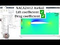
Comprehensive NACA 2412 Airfoil CFD Tutorial with ANSYS Fluent
This detailed tutorial guides you through modeling, meshing, and simulating a NACA 2412 airfoil using ANSYS Fluent. Learn step-by-step how to create geometry, set mesh parameters, run simulations, and analyze lift and drag coefficients, including the impact of varying angle of attack. Practical tips on y-plus calculation and comparison with experimental data enhance your CFD skills.
Complete ANSYS Fluent Tutorial: NACA 2412 Airfoil Simulation and Analysis
Learn how to simulate the NACA 2412 airfoil in ANSYS Fluent step-by-step, from geometry creation and meshing to setting boundary conditions and performing flow analysis. This comprehensive guide includes drag and lift coefficient calculations, flow field visualization, and angle of attack effects, making it ideal for engineering students and CFD practitioners.

2026 Design Industry Shift: AI Skills, Tools & Career Strategy Guide
Discover how AI is transforming the design industry in 2026—from 91% designer AI adoption to 5x salary gaps. Learn the essential skills, new job roles, and portfolio strategies to stay irreplaceable.
Most viewed summaries

A Comprehensive Guide to Using Stable Diffusion Forge UI
Explore the Stable Diffusion Forge UI, customizable settings, models, and more to enhance your image generation experience.

Kolonyalismo at Imperyalismo: Ang Kasaysayan ng Pagsakop sa Pilipinas
Tuklasin ang kasaysayan ng kolonyalismo at imperyalismo sa Pilipinas sa pamamagitan ni Ferdinand Magellan.

Mastering Inpainting with Stable Diffusion: Fix Mistakes and Enhance Your Images
Learn to fix mistakes and enhance images with Stable Diffusion's inpainting features effectively.

Pamamaraan at Patakarang Kolonyal ng mga Espanyol sa Pilipinas
Tuklasin ang mga pamamaraan at patakaran ng mga Espanyol sa Pilipinas, at ang epekto nito sa mga Pilipino.

How to Install and Configure Forge: A New Stable Diffusion Web UI
Learn to install and configure the new Forge web UI for Stable Diffusion, with tips on models and settings.
Found this summary useful?
Take it with you. One click puts it in your own LunaNotes library.
Save to LunaNotes