Introduction
Welcome to our comprehensive tutorial on using Packet Tracer, a powerful network simulation tool that allows networking enthusiasts and professionals alike to emulate network topologies without the need for physical equipment. In this guide, we will walk you through the complete process of setting up a basic network using Packet Tracer, encompassing configuration of routers, PCs, and testing connectivity through practical examples. By the end of this tutorial, you'll be proficient in using Packet Tracer and have a solid understanding of basic network setup.
What is Packet Tracer?
Packet Tracer is a network simulation tool developed by Cisco. It enables the design and visualization of network setups in a user-friendly environment. This powerful software provides:
- Easy emulation of network topologies
- Simulation capabilities for real-time network performance evaluation
- Cost savings by eliminating the need for physical hardware
- Extensive features for practicing Cisco command line interface (CLI) configurations
Setting Up Your First Network
Launching Packet Tracer
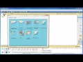
To begin, make sure you have Packet Tracer installed on your device. Open the application to access the device area at the bottom of the interface.
Step 1: Placing Devices
- Add a Router: Click on the Routers icon in the device area, then select the appropriate router from the list, such as 1841.
- Position the Router: Move your mouse to the logical workspace and click to place the router.
- Add PCs: Click on End Devices and select Generic PC to place two PCs in the workspace.
Step 2: Connecting Devices
- Click on Connections in the device area, then choose Copper Cross-Over Cable.
- Connect one end of the cable to PC 0's Fast Ethernet interface and the other end to Router 0's Fast Ethernet 0/0 interface.
- Repeat this step for PC 1, connecting it to Router 0's Fast Ethernet 0/1 interface.
- You can move the devices around for better workspace arrangement.
Configuration of Router and PCs
Once the physical setup of the network is complete, we need to configure the router and PCs to establish communication.
Step 3: Configuring the Router
- Access Router CLI: Click on Router 0, and switch to the CLI tab.
- When prompted, type
noto skip the configuration dialog. - Enter Privileged Exec Mode: Type
enableto access privileged exec mode. - Global Configuration Mode: Enter
config tto switch. - Set Router Hostname: Input
hostname Router0. - Set Enable Secret: Use
enable secret classfor password setup, keeping in mind that this is a placeholder. - Configure Console and VTY Lines: Follow these commands to set console and virtual terminal line passwords:
line con 0 password Cisco login exit line vty 0 4 password Cisco login exit - Fast Ethernet Interface Configuration: Enter the commands to set IP addresses:
interface fastethernet 0/0 ip address 192.168.1.1 255.255.255.0 description Router0 FastEthernet 0/0 no shutdown exit interface fastethernet 0/1 ip address 192.168.1.2 255.255.255.0 description Router0 FastEthernet 0/1 no shutdown exit - Save Configuration: Enter
copy running-config startup-configto save the settings permanently.
Step 4: Configuring PCs
Now, let's configure the two PCs to ensure they can communicate with Router 0.
-
For PC 0
- Click on PC 0, go to the Desktop tab, and select IP Configuration.
- Set:
- IP Address:
192.168.1.2 - Subnet Mask: Default
- Default Gateway:
192.168.1.1
- IP Address:
-
For PC 1
- Click on PC 1 and perform similar IP configuration:
- IP Address:
192.168.1.3 - Subnet Mask: Default
- Default Gateway:
192.168.1.1
- IP Address:
- Click on PC 1 and perform similar IP configuration:
Testing Connectivity with Ping
Once you've configured both the router and PCs, it’s time to confirm the network's functionality using the ping command to test connectivity.
- On PC 0, navigate to the Desktop tab again and click on Command Prompt.
- Type
ping 192.168.1.3(the address of PC 1) and hit Enter. - If everything is configured correctly, you will see success responses indicating that the PCs can communicate.
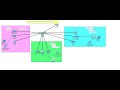
Visualization in Simulation Mode
To visualize the ping packet traveling between devices:
- Switch to Simulation Mode in the toolbar under the Real-Time tab.
- Set filters to show only ICMP packets.
- Click on PC 0, select PC 1, and hit Auto Capture / Play to see the details of the communication.
Conclusion
Congratulations! You have successfully set up a simple network with Packet Tracer, configured the router and PCs, and tested connectivity between devices. This foundational knowledge is crucial for further growth in networking concepts and practices. As you continue exploring Packet Tracer, consider delving into more complex topologies and configurations to enhance your skills.
Next Steps
- Experiment with different network devices in Packet Tracer.
- Explore advanced routing protocols.
- Consider obtaining relevant certification for a deeper understanding of networking.
hello my name is Kevin this video tutorial will walk you through the basics of using Cisco Packet Tracer
Packet Tracer is a very powerful tool that allows you to emulate a neetwork topology without physically building it
with this Nifty piece of software you won't need expensive pieces of equipment or spend hours wiring things together by
the time this video tutorial is over you will know how to set up a simple Network consisting of a router and two PCS
configure routers through the command line interface use simulation mode to visually trace a ping let's
begin to make a simple Network first click the routers icon in the device area at the bottom and choose the 1841
router move your mouse to The Logical workspace and click to place the router next click end devices in the device
area choose the generic PC and place it in the workspace repeat to add a second
PC to connect them click connections and choose the copper crossover
cable click on pc0 and click fast ethernet to to connect the cable to the
PC's fast vast ethernet interface then while in control of the cable connect the other end to router Zero's vast
ethernet 0/0 interface repeat with pc1 and the
remaining fast ethernet interface on router zero feel free to move the equipment
around the workspace you have now physically set up a network in Packet
Tracer now let's configure the network to make it work click router zero a window will come up go to the command
line interface or CLI tab here with this question continue with configuration dialogue type
no we will manually configure the router with commands press return to get started as this
prompt suggests at this prompt type enable to enter privileged exec mode this is similar to root in Unix
systems you will know you are in privil privileged exec mode when you see the router name followed by a number sign
type in config T to enter Global configuration mode type host name router zero to name the router
next type enable secret class to set an encrypted password for logging into privileged exec mode in
real world situations class is obviously not an acceptable password but for the purposes of these tutorials we will use
either class or Cisco for the password configure the password for the console line by entering line con 0
and then password Cisco enter login to enable password
prompting enter exit to return to Global configuration mode configure the password for the
virtual terminal Lines by entering line vty 0 Space 4 and then password
Cisco again enter login to enable the password requirement and then exit to return to configure the fast ethernet
interfaces enter interface and then the interface name in this case we'll start with fast ethernet
0/0 next enter in in IP address 192.168.1.1 space
255.255.255.0 to set this interfaces IP address and subnet mask although optional you may want to add a
description to the interface for later reference by entering in description router Z
fast ethernet 0/0 last enter the command no
shutdown to start the interface exit back to Global config mode repeat with fast ethernet zero SL1
except this time use IP address 192.168 do210 fast ethernet
01 and don't forget to type in no shutdown to enable the interface exit out of interface config
mode and then exit out of global config mode hit enter at this prompt and you will be back at privileged exec mode
enter in Show running Das config to display the current
configuration continuously hit enter to scroll down you will see all the configurations
you just set to save this configuration to the NV Ram so that when the router boots up it
automatically loads it enter in copy running down D config space startup-config
hit enter at this prompt to confirm router configuration is now complete close the router zero
window to configure the PCS first click pc0 go to the desktop tab here click IP
configuration we will will set a static IP set the IP address to 192.168.1.2 then hit tab keep the
default subnet mask hit tab again and enter 192.168.1.1 for the default gateway
close the pc0 window repeat with pc1 except for the IP address use
192.168 do2 do2 and default gateway 192.168 do2
do1 and then close pc1s window by now there should be green dots on the cables near the
devices this means that they are connected let's try pinging pc1 from pc0 click
pc0 go to the desktop Tab and click command prompt this acts just like a DOS prompt
in a Windows operating system for example you can type in ip config and you can see the details of the IP
address subnet mask and default gateway enter the command ping1 192.168 do2 do2 to Ping
pc1 at first you may get a requests timed out but after that the Ping should succeed you can try
again and it should be fine the Ping is successful now let's visually see the
pay with simulation mode near the bottom right corner you will see a tab with a clock labeled real time click the tab
behind it to act activate simulation mode here click edit filters click the show all/ nun boox
once to clear the selections check off icmp and click out of
that on the right side bar click the first yellow envelope with a plus this one this will allow us to choose a
source and destination for our pdu or protocol data unit click
pc0 and then click pc1 an envelope with a randomly assigned a color will appear at pc0 in this case
it's green click autocapture slpl to begin the Ping simulation observe as the pdu travels to
router zero and then to pc1 and then back once it returns back to pc0 the pdu is
verified and checked off which means the Ping was a success done you have now successfully
completed this package Tracer tutorial thanks for watching
Heads up!
This summary and transcript were automatically generated using AI with the Free YouTube Transcript Summary Tool by LunaNotes.
Generate a summary for freeRelated summaries
How to Use Cisco Packet Tracer for Network Simulation
Learn how to set up and configure a simple network using Cisco Packet Tracer with our step-by-step guide.
Designing a Network for XYZ Company: A Step-by-Step Guide
In this video, we tackle the second networking project for XYZ Company, which involves designing a separate network for a new branch. We cover the requirements, including VLAN configuration, DHCP setup, and inter-VLAN routing, ensuring all departments can communicate effectively.

Comprehensive Free CCNA Course Introduction: Networking Basics Explained
Discover the fundamentals of networking through a free CCNA course introduction sponsored by Boson Software. Learn how devices like switches, routers, firewalls, and wireless access points enable communication across networks, from your home setup to the vast internet. Gain insights into the CCNA certification path and how it can kickstart your career as a network engineer.

Complete CCNA 200-301 Course: Network Devices & Fundamentals Explained
This introductory CCNA course video covers essential network devices including routers, switches, firewalls, servers, and clients. Learn their roles in building networks, client-server relationships, and how to prepare for the CCNA 200-301 exam with practical labs, quizzes, and flashcards.
CCNA Routing Fundamentals: Connected and Local Routes Explained
This detailed course video explains key routing concepts for the CCNA exam, focusing on connected and local routes automatically added to Cisco routers. Learn how routers use routing tables to forward packets, understand route matching, and grasp how routers select the most specific routes to deliver or receive packets.
Most viewed summaries

A Comprehensive Guide to Using Stable Diffusion Forge UI
Explore the Stable Diffusion Forge UI, customizable settings, models, and more to enhance your image generation experience.

Kolonyalismo at Imperyalismo: Ang Kasaysayan ng Pagsakop sa Pilipinas
Tuklasin ang kasaysayan ng kolonyalismo at imperyalismo sa Pilipinas sa pamamagitan ni Ferdinand Magellan.

Mastering Inpainting with Stable Diffusion: Fix Mistakes and Enhance Your Images
Learn to fix mistakes and enhance images with Stable Diffusion's inpainting features effectively.

Pamamaraan at Patakarang Kolonyal ng mga Espanyol sa Pilipinas
Tuklasin ang mga pamamaraan at patakaran ng mga Espanyol sa Pilipinas, at ang epekto nito sa mga Pilipino.

How to Install and Configure Forge: A New Stable Diffusion Web UI
Learn to install and configure the new Forge web UI for Stable Diffusion, with tips on models and settings.

If you found this summary useful, consider buying us a coffee. It would help us a lot!