Overview of Circuit Fundamentals for MCAT
Chapter 6 of MCAT Physics focuses on circuits, covering current, resistance, capacitance, and measurement.
1. Electric Current and Conductivity
- Current: Flow of positive charges (conventional current) though electrons actually flow opposite.
- Conductivity (Siemens, S): Measure of a material’s ability to conduct current; inversely related to resistance (Ohms).
- Types:
- Metallic Conductivity: Free-flowing electrons in metals.
- Electrolytic Conductivity: Movement of ions in solutions (depends on ion concentration).
- Current formula: (I = \frac{Q}{\Delta t}) (Charge per time, units = Amps).
- Currents: Direct Current (DC) flows one way; Alternating Current (AC) changes direction (MCAT focuses on DC).
For a deeper understanding, see Understanding Electricity: The Basics of Current, Potential Difference, and Resistance.
2. Voltage and Potential Difference
- Voltage = Potential difference; drives current from higher to lower potential.
- Acts like potential energy in an electric field.
3. Circuit Laws
- Kirchhoff's Junction Rule: Total current entering junction equals total current leaving.
- Kirchhoff's Loop Rule: Sum of voltage changes in a closed loop equals zero, accounting for batteries and resistors.
These laws are fundamental for circuit analysis, detailed in Understanding Ohm's Law and Kirchhoff's Laws in Electrical Circuits.
4. Resistance
- Calculated as (R = \rho \frac{L}{A})
- (\rho): resistivity (material dependent)
- (L): length of resistor (longer increases resistance)
- (A): cross-sectional area (larger decreases resistance)
- Ohm’s Law: (V = IR) relates voltage, current, and resistance.
5. Power in Circuits
- Power dissipated by resistors: (P = IV = I^2 R = \frac{V^2}{R})
- Useful for calculating energy loss across resistors.
6. Resistors in Series and Parallel
- Series:
- Current is constant through all resistors.
- Total resistance is sum: (R_{total} = R_1 + R_2 + \cdots)
- Voltage drop across each adds to total voltage.
- Parallel:
- Voltage drop is constant across all branches.
- Total resistance computed by reciprocal sum: (\frac{1}{R_{total}}=\frac{1}{R_1}+\frac{1}{R_2}+\cdots)
- Adding more branches reduces total resistance.
7. Capacitance and Capacitors
- Capacitance (C = \frac{Q}{V}) measures ability to store charge.
- Units are farads (F).
- Capacitor symbol: two parallel lines; differs from battery symbol.
- Capacitance formula for parallel plate capacitors:
- (C = \epsilon_0 \frac{A}{d}), where (\epsilon_0) is permittivity, (A) area, (d) distance between plates.
- Dielectric materials increase capacitance by factor (k) (dielectric constant): (C' = kC).
- Stored energy: (U=\frac{1}{2} C V^2).
For additional insight, consider Understanding Conductors and Capacitors in Electric Circuits.
8. Capacitors in Series and Parallel
- Series:
- Total capacitance adds reciprocally: (\frac{1}{C_{total}} = \frac{1}{C_1} + \frac{1}{C_2} + \cdots)
- Longer effective distance reduces capacitance.
- Parallel:
- Capacitors add directly: (C_{total} = C_1 + C_2 + \cdots)
- Increases total plate area for charge storage.
9. Measurement Tools for Circuits
- Ammeter: Measures current; connected in series; circuit must be on.
- Voltmeter: Measures voltage drop; connected in parallel; circuit must be on.
- Ohmmeter: Measures resistance; circuit must be off to avoid interference.
This summary equips MCAT students with foundational understanding and mathematical tools to analyze circuits confidently. Mastery of these principles helps in tackling a variety of MCAT questions related to electric circuits. For a comprehensive preparation guide, see Comprehensive Overview of Current Electricity for NEET 2025 and enhance your study approach.
hi everyone today we're going over chapter six of physics for the mcat which covers circuits
chapter 6.1 is about current which is defined as the movement of positive charges however we know now
that um current is actually caused by the movement of electrons which are negative
charges so if you see current going in a specific direction just know that the
electrons are actually moving in the opposite direction a useful concept is that of conductivity
which is just how much current can this material conduct and this is in units of siemens
also known as s or one over ohms the reason why this is important is because um ohms is the unit for
resistance which is just the opposite of conductivity it's the ability to resist
a current from flowing and so it's pretty intuitive that conductivity would be the reciprocal of um resistance
there are two main types of conductivity there's metallic conductivity which is just the conductivity of a
metal metals are usually described as a sea of electrons
because all of the atoms in the metal are effectively sharing all of the electrons and the electrons
are fairly free-flowing which is why metals are so conductive because
the electrons can flow from one side to the other really easily the other type of conductivity is known
as electrolytic conductivity um electrolytic conductivity is when ions are dissolved
in a certain solution and the ions themselves have charges and so they're the ones that will be moving
around to create a current or a movement of charge
and this type of conductivity is concentration based so for example if you dissolved nacl
which is table salt into a cup of water the more salt that you dissolve
the more conductive the solution will be which makes sense because the more um nacl you dissolve the more
positive and negative charges you have that are able to move around and create a current so current is
um denoted with the letter capital i and it is defined as q over delta t where q is the amount of charge and
delta t is time so current is defined as how many charges are moving past a certain point
over a certain amount of time and this is in units of amps so there are two types of currents
one is called direct current which is just current moving in one direction and the other is called alternating
current so alternating current is actually what most of our um appliances use now
however the mcat will not focus on alternating current we'll only be talking about direct current to make
things easier so another concept that's useful is the
idea of potential difference so we discussed in the last chapter what a volt
is and this is a really really important concept in this chapter um so a potential
difference is also known as the electron motive force denoted by these things um but it is also what's
known as voltage so voltage is the same thing as potential difference
which means that if you have two points in space and one has a higher potential and the
other has a lower potential then your charged particle is going to want to move from the higher potential
to the lower potential and so i like to think of voltage as a kind
of potential energy um kind of like if you raise an object off the ground and now it has more potential energy
and wants to fall toward earth um this is how i think about voltage as well and so volt als though it's called
electron motive force voltage is not a real type of um force it's actually a measure of kind of potential energy so
now that we know these things we can talk about some of the rules that govern circuits
so our first rule is going to be kirchhoff's junction rule so all this rule means is that the
amount of current that goes into a junction is the same as the amount of current going outside
going out of the junction so if you look at this junction that i drew here um there's more to the
circuit i just didn't draw all of it so if we have this one path going in let's say that this one path is
maybe 5 amps then we know that the amount going in is the same as the amount going out so the other two
branches if this one was three amps then this one must be
two amps and um that's all there is to the junction rule and it makes intuitive sense if you have
five charges going in you have to have five charges going back out the next rule is the loop rule
so all circuits are going to be loops and so if you look at the circuit that i drew here first of all this
um the symbol over here is how you denote a battery typically the long side will be the
positive side and the short side will be the negative side um but a battery has to have a positive
and a negative side and what a battery does is that it drives all of the charges in a circuit
from one side to the other side so in this case this is the positive side and so there are no charges on
there are no electrons on that side and the side is the negative side which means that
all the electrons are built up on the side and so this gives the positive side of
the battery a um very high uh voltage and the negative side of the battery
a much lower voltage and so all that the loop rule means is that when we go around this loop
um all of these 10 volts have to be accounted for somewhere because you you don't just change
voltage for no reason so when we go around the circuit we can see that we have two
of these squiggly line things these squiggly line things are what are known as resistors and
resistors cause um voltage to be dissipated so when we go around this loop we can say
that at the first resistor maybe we lose 5 volts or we have a voltage drop
of 5 volts and at the second resistor we also drop 5 volts and so the loop rule just says that
everything has to be accounted for so if we start here at 10 volts then we lose 5 volts and then we lose
another 5 volts then that makes sense so when we get back here we have zero volts
chapter 6.2 is about resistance and you can calculate resistance with this equation it's going to be in units of
ohms and so resistance is defined by rho this row is going to be a constant
it's called the resistivity and this is going to be a different constant for every kind of material
l is the length of your resistor so if you think of a resistor as kind of like a filter then the longer
this filter is the more distance it has to filter stuff out and so
the longer it is the more resistant it will be and this is divided by area so if you
think about it once again as a filter then the wider this filter is the more charge is going to be able to go through
it at any given time and so the bigger the area then the less resistance something has
and the most important equation in this entire chapter i think is ohm's law and ohm's law is
equal to v equal to ir where v is voltage i is current and r is resistance and this
equation governs basically all of circuits and you need to know this equation it
might be more intuitive to think about it as i which is current equals voltage over
resistance um it might be more helpful to think about it this way because current will be bigger if the voltage is
bigger and current will be smaller if the resistance is bigger um but v equals i are very very important
and another equation that's kind of helpful is power so in circuits we think about power not
as um like doing something but we think of it more in the context of power that is
dissipated and power that is dissipated specifically by a resistor
so we talked about in this picture up here that um this resistor is basically causing a voltage drop of 5
volts and so if it's taking away voltage then it has to dissipate power
and so in circuits power is defined as p equals iv um there are some obscene mnemonics to
remember this and this is also equal to i squared equals r which we can find simply by
plugging in v equals ir to p equals iv a harmonic for this is twinkle twinkle
little star p equals i squared r and this is also equal to
v squared over r but you can find both of these other forms just by plugging in v equals ir
to p equals iv and this is how you find how much power is dissipated by each resistor
so if we're looking at our circuit above we can plug in the current which i didn't give you for the circuit
and then the voltage here we're going to look at what's going to happen if you have multiple resistors
in the same circuit and the difference between resistors in series and resistors in parallel
is another very important distinction in this chapter so first off a resistance in series is
when you have the multiple resistors just lined up in a row such that
if you had a charge then this charge must go through all of the resistors in order to get to
the other side resistance in parallel means that if you have a charge
um over here wanting to get to the other side you can choose any path so you can choose to go through
r1 r2 or r3 um it's not important here that i drew
resistor one closest to the um entrance and the exit of this circuit part
you can draw these anywhere um the only important part is that your charges can choose to go through
um r1 r2 or r3 and so if you have a resistor if you have resistors in series um we
can think about the equation v equals ir and we know that um current we know that current is going to
be constant throughout this entire circuit because if you have a charge or if you
have three charges over here on the other side you're always going to end up with three charges
um so we can just ignore this i term for now and if we think about the voltage drops
so the total voltage drop for resistors in series is going to be that the total voltage
drop is equal to all of the voltage drops added together and this is because
if you have a voltage drop of let's say two volts here one volt here and
two volts here then the total then the total voltage drop will um be the sum of all of these
because your charge is going to have to go through each and every one of these to get to the other side
um and so it follows that the total resistance is going to be also all of the resistances added
together following the equation v equals ir and so um this is really important if let's say
you had a question that said um the resistance of r1 is going to be 3 ohms and of r2
it's going to be 2 ohms and of r3 it's going to be 1 ohm then it wants to know the total
resistance of the circuit then you would just add them all up and you would say that the total resistance
is going to be equal to 6 ohms you can also do this if it tells you the voltage drop of each
resistor or if it tells you the total voltage drop and asks you to go back and find
the voltage drops of each individual resistor so it gets a little bit more complicated
with when we think about resistors in parallel um so first off if we want to think about the voltage drops of
resistors in parallel we can think that the voltage drop of v1 um which is the drop of r1 is
the same as for r2 and it's the same as for r3 so we're not going to be adding them together
we're going to say that they're equal to each other and this is because let's say that the voltage up here is 8
volts and the voltage down here is 4 volts then that means no matter which path the
charge took it had a voltage drop of 4 volts so r3 is going to have a voltage drop of
4 volts so is r2 and so is r1 um because the charge only takes one of the paths
to get from one side to another and then um the second equation which is that the total resistance or
rather the reciprocal of the total resistance is equal to the reciprocal of each individual
resistor and if you think about this a little what this means is that the more
resistors you add um the less resistance you actually have which makes a lot of sense actually
because if you think about resistors as um like blocking the current then if you add more paths so
if you only had r1 here then all of your charges can only go through r1 which will slow them down
significantly but then if you add two more resistors that's two more paths your charge can go down
which means that there's actually less resistance even though there are more resistors
and so these equations are also similarly useful so like if you were given the
resistances of each individual resistor and asked to add them all up together into a total um another way these
equations can be used is let's say i'm drawing a hypothetical circuit
where here we have one resistor r1 and here we have r2 and here we have
r3 and we have current going kind of this way this is not how you draw circuit
notation you wouldn't put an arrow here um i'm just adding it for clarity and so if we wanted to know um the total
resistance of this entire circuit element then we would first want to add up
r2 and r3 in parallel and we know they're in parallel because when once you get here you can either
choose to go this way or that way um and so we would add them up using that the total resistance i'm going to
call this r4 is equal to 1 over r2 plus 1 over r3 or this is 1 over
r4 sorry um and then we can go and redraw the circuit because we've now added r2 and r3
together so now we have r1 and r4 and r1 and r4 are now in series with
each other and so then we can add up the total resistance of
this entire circuit element is equal to r1 plus r4 and that's one of the ways that you
would use all of these equations chapter 6.3 is about capacitance and capacitors
so capacitance is just the ability for anything to hold a charge um capacitance is calculated with this
equation where c is the capacitance of a particular capacitor
and it's equal to q which is charge over v which is voltage so what this means is
that if you have something with a capacitance of say one ferad a ferrite is the unit of a
capacitor and your entire circuit has a voltage of let's say five then you're going to be
able to um hold five charges in your capacitor but let's say your voltage is now 15
um because the voltage of a circuit can change based on the battery so if you now add a
stronger battery this capacitor is now going to be able to hold more charge
so capacitance is the measure of how many charges it can hold per voltage of the circuit and not a
direct measure of how many charges it can hold and a ferret is in units of
c which is coulombs this is not capacitance this is coulombs over volts because coulombs is the unit
for charge so capacitors are drawn um this way with two parallel lines
this looks kind of like a battery but don't get this confused with a battery a battery will always have one short
line and one long line another difference between um a capacitor
and a battery is that a capacitor has to be charged by a battery um and a capacitor can only hold charge
for a very limited amount of time a capacitor doesn't have energy on its own the
um only ability of a capacitor is to hold charges away from each other
and also always in a capacitor the um charge of the negative side has to be equal to the positive side
so if the side is let's say five if you have five charges here then you have to have negative five
here and this is because in order for this to happen um all of the charges must be driven
from the negative side to the positive side and then
so therefore the negative side will have the same amount of deficiency of charge that the positive side
has charge if that didn't make sense don't worry this is not very important what's important is this equation here
so capacitance can also be calculated as e naught which is this constant here um you'll be given
this constant don't worry about remembering it and multiplied by the area of the
capacitor so this is multiplied by area because the larger the area of your capacitor
plate um the more charge it can hold and this is divided by the distance between the
plates so the closer together your plates are the higher the capacitance and this is
because each plate has its own electric field and so the closer um the plates are the more
the the stronger the fields will be um yeah so these are the two equations you would use to calculate capacitance
um another concept is that of a dielectric material um which is also known as an insulator
so this equation here um c prime which is your new altered capacitance as a result of the
dielectric oh so dielectric material is one you can place
in the middle of your capacitor and this alters the capacitance of your capacitor because
essentially the dielectric takes up a bunch of the free space here and so it effectively brings the
capacitors closer together because there's less space between
and so the new altered capacitance is going to be equal to k which is a constant multiplied by the original
capacitance and so this k will always be greater than 1 which means your new
altered capacitance will always be greater than the old one um if it was less than one then it
wouldn't be a dielectric material anymore i forgot to mention this so
the potential energy that's stored in a capacitor is equal to u equals one half
c v squared where c is the capacitance and v squared is the voltage so i think of this
kind of like the equation one equals m v squared that's just how i remember it um where
mass is kind of like capacitance and velocity is kind of like voltage this always made sense to me
similar to four resistors we can also have capacitors in series and in parallel
but these equations are going to be the opposite of those seen for resistors and so to understand why this makes
sense we can look at the equation that we wrote for capacitance which is e naught which is a constant
multiplied by area over a distance and so when we look at capacitors in series which means that if
you had a charge it would go through all three of these capacitors um effectively what is going to happen is
that this charge is going to have to go through three separate distances um there's
going to be d1 d2 and d3 so we have to add up all of these distances
and as we can see in this equation the greater the total distance the less the total capacitance which is
why we use this equation which means that the more capacitors you add in series
the less capac the less total capacitance there is going to be um and if we think about the situation
in parallel which in resistors we used the um this equation of reciprocals
when we look at capacitors we're going to just add them all up and this is because if you had a charge
and it can choose to go through each of the paths then it's only going to go through one distance so this
distance term is unchanged however you have a situation where charge can build up on each of these plates
which means actually if you have three capacitors then three times the charge can be built up and therefore we have a
case where the capacitance equals all of the individual capacitances added together
if you're wondering why we can't also add up the areas in the case of capacitors in series we
can think back to our equation c equals q over v um where v is voltage and q is the
amount of charge and so if we think that for both of these series
if for both of these systems of capacitors that we have a voltage drop of three
which means that up here we have three volts and down here we have zero volts this means that in the case in parallel
each of these capacitors is going to have a voltage drop of three so far capacitance is 1
then we can have 3 q or q is in units of coulombs over 3 volts
which gives us more charge but on the other hand in series we're going to have three
separate voltage drops so each voltage drop if we have a capacitance of one
is going to be one coulomb over one volt and so that's why even though they're in series
it doesn't mean they're going to be able to hold more charge chapter 6.4 is about meters
which are all the different devices that you can use to measure your components of a circuit
this is pretty straightforward an ammeter measures current in amps a volt meter measures
voltage drops in volts and for both an ammeter and a volt meter you're going to want to turn
your circuit on because you can't measure current unless the circuit is running
and you also can't measure a voltage drop unless your circuit is running because if your circuit isn't running
then there is going to be no voltage drop for an ohmmeter it measures resistance
in ohms and for an ohmmeter your circuit should be off
because for an ohmmeter your ohmmeter is going to run its own current through the resistor to find out how much
resistivity there is and so thank you so much for watching i hope that this video helped you out
and yeah see you in the next chapter
Electric current is the flow of positive charge per unit time (measured in amperes), typically carried by electrons moving opposite the conventional current direction. Conductivity measures a material's ability to conduct current, expressed in siemens (S), and is inversely related to resistance; different materials (metals vs. electrolytes) exhibit different types of conductivity.
Kirchhoff's Junction Rule states that the total current entering a junction equals the total current leaving, ensuring charge conservation. Kirchhoff's Loop Rule dictates that the sum of voltage changes around any closed loop is zero, accounting for voltage rises and drops from batteries and resistors. Together, these laws allow systematic analysis of complex circuits by applying current and voltage constraints.
In series, resistors add directly: the total resistance is the sum of individual resistances (R_total = R1 + R2 + ...), with the same current flowing through each. In parallel, the reciprocal of the total resistance equals the sum of reciprocals of each resistor (1/R_total = 1/R1 + 1/R2 + ...), resulting in a total resistance that decreases as more branches are added, while voltage across each is constant.
Capacitance depends on the plate area (A), the distance between plates (d), and the permittivity of free space (ε₀), calculated as C = ε₀ * A / d. Inserting a dielectric material with dielectric constant k between the plates increases capacitance by a factor of k (C' = kC) by reducing the effective electric field, allowing the capacitor to store more charge at the same voltage.
An ammeter measures current and must be connected in series with the circuit element; the circuit must be powered on. A voltmeter measures voltage drop and connects in parallel across components, also requiring the circuit to be on. An ohmmeter measures resistance and must be connected with the circuit power off to prevent interference from current flow, ensuring accurate resistance readings.
Power dissipated by a resistor can be computed using any of the three formulas: P = IV (current times voltage), P = I²R (current squared times resistance), or P = V²/R (voltage squared divided by resistance). These formulas help determine energy loss as heat in the resistor, which is crucial for understanding circuit efficiency and component ratings.
Keep this summary
Save it to LunaNotes and it becomes a real note in your library — editable, searchable, and ready to turn into flashcards or a diagram. Free to start.
Save to LunaNotesOr summarise for another video.
This summary and transcript were automatically generated using AI with the Free YouTube transcript summary tool by LunaNotes.
Related summaries
Understanding Circuits: Key Concepts and Theories
Explore the fundamentals of electrical circuits, current flow, and more with this in-depth guide.

Understanding Electricity: The Basics of Current, Potential Difference, and Resistance
Learn the fundamentals of electricity, including current, voltage, and resistance, crucial for your physics studies.
Understanding Conductors and Capacitors in Electric Circuits
Explore the critical concepts of conductors, capacitors, and electric circuits in this comprehensive guide.
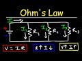
Understanding Ohm's Law and Kirchhoff's Laws in Electrical Circuits
This video explains Ohm's Law, illustrating the relationship between voltage, current, and resistance with practical examples. It also covers calculating current and voltage in series and parallel resistor circuits while introducing Kirchhoff's Voltage and Current Laws for analyzing complex circuits.

MCAT Physics Waves & Sound: Comprehensive Chapter 7 Summary
Explore key concepts of waves and sound for the MCAT, including sinusoidal waves, wave properties, Doppler effect, and sound intensity. Understand wave types, interference, standing waves, and applications like ultrasounds with precise equations and examples for effective exam preparation.
Most viewed summaries

A Comprehensive Guide to Using Stable Diffusion Forge UI
Explore the Stable Diffusion Forge UI, customizable settings, models, and more to enhance your image generation experience.

Kolonyalismo at Imperyalismo: Ang Kasaysayan ng Pagsakop sa Pilipinas
Tuklasin ang kasaysayan ng kolonyalismo at imperyalismo sa Pilipinas sa pamamagitan ni Ferdinand Magellan.

Mastering Inpainting with Stable Diffusion: Fix Mistakes and Enhance Your Images
Learn to fix mistakes and enhance images with Stable Diffusion's inpainting features effectively.

Pamamaraan at Patakarang Kolonyal ng mga Espanyol sa Pilipinas
Tuklasin ang mga pamamaraan at patakaran ng mga Espanyol sa Pilipinas, at ang epekto nito sa mga Pilipino.

How to Install and Configure Forge: A New Stable Diffusion Web UI
Learn to install and configure the new Forge web UI for Stable Diffusion, with tips on models and settings.
Found this summary useful?
Take it with you. One click puts it in your own LunaNotes library.
Save to LunaNotes